DF38602RFT10 Renesas Electronics America, DF38602RFT10 Datasheet - Page 87
DF38602RFT10
Manufacturer Part Number
DF38602RFT10
Description
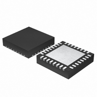
MCU 3V 16K 32-QFN
Manufacturer
Renesas Electronics America
Series
H8® H8/300H SLPr
Datasheet
1.DF38602RFT10.pdf
(554 pages)
Specifications of DF38602RFT10
Core Processor
H8/300H
Core Size
16-Bit
Speed
10MHz
Connectivity
I²C, IrDA, SCI, SSU
Peripherals
POR, PWM, WDT
Number Of I /o
13
Program Memory Size
16KB (16K x 8)
Program Memory Type
FLASH
Ram Size
1K x 8
Voltage - Supply (vcc/vdd)
2.7 V ~ 3.6 V
Data Converters
A/D 6x10b
Oscillator Type
Internal
Operating Temperature
-20°C ~ 75°C
Package / Case
32-QFN
Lead Free Status / RoHS Status
Contains lead / RoHS non-compliant
Eeprom Size
-
Other names
HD64F38602RFT10
HD64F38602RFT10
HD64F38602RFT10
Available stocks
Company
Part Number
Manufacturer
Quantity
Price
Company:

Part Number:
DF38602RFT10V
Manufacturer:
Renesas Electronics America
Quantity:
135


3.5.2
Internal interrupts generated from the on-chip peripheral modules have the following features:
• For each on-chip peripheral module, there are flags that indicate the interrupt request status,
3.6
NMI interrupts are accepted at all times except in the reset state. In the case of IRQ interrupts and
on-chip peripheral module interrupts, an enable bit is provided for each interrupt. Clearing an
enable bit to 0 disables the corresponding interrupt request. Interrupt sources for which the enable
bits are set to 1 are controlled by the interrupt controller.
Figure 3.2 shows a block diagram of the interrupt controller. Figure 3.3 shows the flow up to
interrupt acceptance.
Interrupt operation is described as follows.
1. If an interrupt source whose interrupt enable register bit is set to 1 occurs, an interrupt request
2. When the interrupt controller receives an interrupt request, it sets the interrupt request flag.
3. From among the interrupts with interrupt request flags set to 1, the interrupt controller selects
4. The interrupt controller checks the I bit of CCR. If the I bit is 0, the selected interrupt request
5. If the interrupt request is accepted, after processing of the current instruction is completed,
6. The I bit of CCR is set to 1, masking further interrupts.
7. The vector address corresponding to the accepted interrupt is generated, and the interrupt
and enable bits that select enabling or disabling of these interrupts. Internal interrupts can be
controlled independently. If an enable bit is set to 1, an interrupt request is sent to the interrupt
controller.
is sent to the interrupt controller.
the interrupt request with the highest priority and holds the others pending (see table 3.1).
is accepted; if the I bit is 1, the interrupt request is held pending.
both PC and CCR are pushed onto the stack. The state of the stack at this time is shown in
figure 3.5. The PC value pushed onto the stack is the address of the first instruction to be
executed upon return from interrupt handling.
handling routine located at the address indicated by the contents of the vector address is
executed.
Internal Interrupts
Operation
Rev. 3.00 May 15, 2007 Page 53 of 516
Section 3 Exception Handling
REJ09B0152-0300
Related parts for DF38602RFT10
Image
Part Number
Description
Manufacturer
Datasheet
Request
R

Part Number:
Description:
KIT STARTER FOR M16C/29
Manufacturer:
Renesas Electronics America
Datasheet:

Part Number:
Description:
KIT STARTER FOR R8C/2D
Manufacturer:
Renesas Electronics America
Datasheet:

Part Number:
Description:
R0K33062P STARTER KIT
Manufacturer:
Renesas Electronics America
Datasheet:

Part Number:
Description:
KIT STARTER FOR R8C/23 E8A
Manufacturer:
Renesas Electronics America
Datasheet:

Part Number:
Description:
KIT STARTER FOR R8C/25
Manufacturer:
Renesas Electronics America
Datasheet:

Part Number:
Description:
KIT STARTER H8S2456 SHARPE DSPLY
Manufacturer:
Renesas Electronics America
Datasheet:

Part Number:
Description:
KIT STARTER FOR R8C38C
Manufacturer:
Renesas Electronics America
Datasheet:

Part Number:
Description:
KIT STARTER FOR R8C35C
Manufacturer:
Renesas Electronics America
Datasheet:

Part Number:
Description:
KIT STARTER FOR R8CL3AC+LCD APPS
Manufacturer:
Renesas Electronics America
Datasheet:
Part Number:
Description:
KIT STARTER FOR RX610
Manufacturer:
Renesas Electronics America
Datasheet:

Part Number:
Description:
KIT STARTER FOR R32C/118
Manufacturer:
Renesas Electronics America
Datasheet:

Part Number:
Description:
KIT DEV RSK-R8C/26-29
Manufacturer:
Renesas Electronics America
Datasheet:

Part Number:
Description:
KIT STARTER FOR SH7124
Manufacturer:
Renesas Electronics America
Datasheet:

Part Number:
Description:
KIT STARTER FOR H8SX/1622
Manufacturer:
Renesas Electronics America
Datasheet:

Part Number:
Description:
KIT DEV FOR SH7203
Manufacturer:
Renesas Electronics America
Datasheet: