DF38602RFT10 Renesas Electronics America, DF38602RFT10 Datasheet - Page 27
DF38602RFT10
Manufacturer Part Number
DF38602RFT10
Description
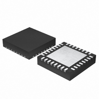
MCU 3V 16K 32-QFN
Manufacturer
Renesas Electronics America
Series
H8® H8/300H SLPr
Datasheet
1.DF38602RFT10.pdf
(554 pages)
Specifications of DF38602RFT10
Core Processor
H8/300H
Core Size
16-Bit
Speed
10MHz
Connectivity
I²C, IrDA, SCI, SSU
Peripherals
POR, PWM, WDT
Number Of I /o
13
Program Memory Size
16KB (16K x 8)
Program Memory Type
FLASH
Ram Size
1K x 8
Voltage - Supply (vcc/vdd)
2.7 V ~ 3.6 V
Data Converters
A/D 6x10b
Oscillator Type
Internal
Operating Temperature
-20°C ~ 75°C
Package / Case
32-QFN
Lead Free Status / RoHS Status
Contains lead / RoHS non-compliant
Eeprom Size
-
Other names
HD64F38602RFT10
HD64F38602RFT10
HD64F38602RFT10
Available stocks
Company
Part Number
Manufacturer
Quantity
Price
Company:

Part Number:
DF38602RFT10V
Manufacturer:
Renesas Electronics America
Quantity:
135


Section 16 I
Figure 16.1 Block Diagram of I
Figure 16.2 External Circuit Connections of I/O Pins ................................................................ 313
Figure 16.3 I
Figure 16.4 I
Figure 16.5 Master Transmit Mode Operation Timing (1) ......................................................... 330
Figure 16.6 Master Transmit Mode Operation Timing (2) ......................................................... 330
Figure 16.7 Master Receive Mode Operation Timing (1)........................................................... 332
Figure 16.8 Master Receive Mode Operation Timing (2)........................................................... 333
Figure 16.9 Slave Transmit Mode Operation Timing (1) ........................................................... 334
Figure 16.10 Slave Transmit Mode Operation Timing (2) ......................................................... 335
Figure 16.11 Slave Receive Mode Operation Timing (1)........................................................... 336
Figure 16.12 Slave Receive Mode Operation Timing (2)........................................................... 337
Figure 16.13 Clock Synchronous Serial Transfer Format .......................................................... 337
Figure 16.14 Transmit Mode Operation Timing......................................................................... 338
Figure 16.15 Receive Mode Operation Timing .......................................................................... 339
Figure 16.16 Block Diagram of Noise Conceler......................................................................... 340
Figure 16.17 Sample Flowchart for Master Transmit Mode....................................................... 341
Figure 16.18 Sample Flowchart for Master Receive Mode ........................................................ 342
Figure 16.19 Sample Flowchart for Slave Transmit Mode......................................................... 343
Figure 16.20 Sample Flowchart for Slave Receive Mode .......................................................... 344
Figure 16.21 Timing of Bit Synchronous Circuit ....................................................................... 346
Section 17 A/D Converter
Figure 17.1 Block Diagram of A/D Converter ........................................................................... 349
Figure 17.2 External Trigger Input Timing ................................................................................ 353
Figure 17.3 Example of A/D Conversion Operation .................................................................. 355
Figure 17.4 Flowchart of Procedure for Using A/D Converter (Polling by Software) ............... 356
Figure 17.5 Flowchart of Procedure for Using A/D Converter (Interrupts Used) ...................... 356
Figure 17.6 A/D Conversion Accuracy Definitions (1) .............................................................. 358
Figure 17.7 A/D Conversion Accuracy Definitions (2) .............................................................. 358
Figure 17.8 Example of Analog Input Circuit ............................................................................ 359
Section 18 Comparators
Figure 18.1 Block Diagram of Comparators............................................................................... 361
Figure 18.2 Hysteresis/Non-Hysteresis Selection by CDR......................................................... 366
Figure 18.3 Procedure for Setting Interrupt (1) .......................................................................... 367
Figure 18.4 Procedure for Setting Interrupt (2) .......................................................................... 368
Section 19 Power-On Reset Circuit
Figure 19.1 Power-On Reset Circuit........................................................................................... 369
Figure 19.2 Power-On Reset Circuit Operation Timing ............................................................. 370
2
2
2
C Bus Interface 2 (IIC2)
C Bus Formats ...................................................................................................... 328
C Bus Timing........................................................................................................ 328
2
C Bus Interface 2..................................................................... 312
Rev. 3.00 May 15, 2007 Page xxv of xxxii
Related parts for DF38602RFT10
Image
Part Number
Description
Manufacturer
Datasheet
Request
R

Part Number:
Description:
KIT STARTER FOR M16C/29
Manufacturer:
Renesas Electronics America
Datasheet:

Part Number:
Description:
KIT STARTER FOR R8C/2D
Manufacturer:
Renesas Electronics America
Datasheet:

Part Number:
Description:
R0K33062P STARTER KIT
Manufacturer:
Renesas Electronics America
Datasheet:

Part Number:
Description:
KIT STARTER FOR R8C/23 E8A
Manufacturer:
Renesas Electronics America
Datasheet:

Part Number:
Description:
KIT STARTER FOR R8C/25
Manufacturer:
Renesas Electronics America
Datasheet:

Part Number:
Description:
KIT STARTER H8S2456 SHARPE DSPLY
Manufacturer:
Renesas Electronics America
Datasheet:

Part Number:
Description:
KIT STARTER FOR R8C38C
Manufacturer:
Renesas Electronics America
Datasheet:

Part Number:
Description:
KIT STARTER FOR R8C35C
Manufacturer:
Renesas Electronics America
Datasheet:

Part Number:
Description:
KIT STARTER FOR R8CL3AC+LCD APPS
Manufacturer:
Renesas Electronics America
Datasheet:
Part Number:
Description:
KIT STARTER FOR RX610
Manufacturer:
Renesas Electronics America
Datasheet:

Part Number:
Description:
KIT STARTER FOR R32C/118
Manufacturer:
Renesas Electronics America
Datasheet:

Part Number:
Description:
KIT DEV RSK-R8C/26-29
Manufacturer:
Renesas Electronics America
Datasheet:

Part Number:
Description:
KIT STARTER FOR SH7124
Manufacturer:
Renesas Electronics America
Datasheet:

Part Number:
Description:
KIT STARTER FOR H8SX/1622
Manufacturer:
Renesas Electronics America
Datasheet:

Part Number:
Description:
KIT DEV FOR SH7203
Manufacturer:
Renesas Electronics America
Datasheet: