DF38602RFT10 Renesas Electronics America, DF38602RFT10 Datasheet - Page 131
DF38602RFT10
Manufacturer Part Number
DF38602RFT10
Description
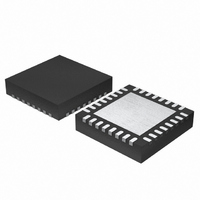
MCU 3V 16K 32-QFN
Manufacturer
Renesas Electronics America
Series
H8® H8/300H SLPr
Datasheet
1.DF38602RFT10.pdf
(554 pages)
Specifications of DF38602RFT10
Core Processor
H8/300H
Core Size
16-Bit
Speed
10MHz
Connectivity
I²C, IrDA, SCI, SSU
Peripherals
POR, PWM, WDT
Number Of I /o
13
Program Memory Size
16KB (16K x 8)
Program Memory Type
FLASH
Ram Size
1K x 8
Voltage - Supply (vcc/vdd)
2.7 V ~ 3.6 V
Data Converters
A/D 6x10b
Oscillator Type
Internal
Operating Temperature
-20°C ~ 75°C
Package / Case
32-QFN
Lead Free Status / RoHS Status
Contains lead / RoHS non-compliant
Eeprom Size
-
Other names
HD64F38602RFT10
HD64F38602RFT10
HD64F38602RFT10
Available stocks
Company
Part Number
Manufacturer
Quantity
Price
Company:

Part Number:
DF38602RFT10V
Manufacturer:
Renesas Electronics America
Quantity:
135


5.6
5.6.1
When a SLEEP instruction is executed in active (high-speed) mode or active (medium-speed)
mode while the SSBY and TMA3 bits in SYSCR1 and the LSON bit in SYSCR1 are cleared to 0,
a transition is made to standby mode. At the same time, pins go to the high-impedance state
(except pins for which the pull-up MOS is designated as on). Figure 5.2 shows the timing in this
case.
5.6.2
(1)
When an external input signal such as NMI, IRQ0, IRQ1, or IRQAEC is input, both the high- and
low-level widths of the signal must be at least two cycles of system clock φ or subclock φ
(referred to together in this section as the internal clock). As the internal clock stops in standby
mode and watch mode, the width of external input signals requires careful attention when a
transition is made via these operating modes. Ensure that external input signals conform to the
conditions stated in (3), Recommended Timing of External Input Signals, below.
φ
Internal data bus
Pins
When External Input Signal Changes before/after Standby Mode or Watch Mode
Standby Mode Transition and Pin States
Notes on External Input Signal Changes before/after Standby Mode
Usage Notes
Figure 5.2 Standby Mode Transition and Pin States
Active (high-speed) mode or active (medium-speed) mode
SLEEP instruction fetch
SLEEP instruction execution
Port output
Next instruction fetch
Rev. 3.00 May 15, 2007 Page 97 of 516
processing
Internal
Section 5 Power-Down Modes
High-impedance
Standby mode
REJ09B0152-0300
SUB
Related parts for DF38602RFT10
Image
Part Number
Description
Manufacturer
Datasheet
Request
R

Part Number:
Description:
KIT STARTER FOR M16C/29
Manufacturer:
Renesas Electronics America
Datasheet:

Part Number:
Description:
KIT STARTER FOR R8C/2D
Manufacturer:
Renesas Electronics America
Datasheet:

Part Number:
Description:
R0K33062P STARTER KIT
Manufacturer:
Renesas Electronics America
Datasheet:

Part Number:
Description:
KIT STARTER FOR R8C/23 E8A
Manufacturer:
Renesas Electronics America
Datasheet:

Part Number:
Description:
KIT STARTER FOR R8C/25
Manufacturer:
Renesas Electronics America
Datasheet:

Part Number:
Description:
KIT STARTER H8S2456 SHARPE DSPLY
Manufacturer:
Renesas Electronics America
Datasheet:

Part Number:
Description:
KIT STARTER FOR R8C38C
Manufacturer:
Renesas Electronics America
Datasheet:

Part Number:
Description:
KIT STARTER FOR R8C35C
Manufacturer:
Renesas Electronics America
Datasheet:

Part Number:
Description:
KIT STARTER FOR R8CL3AC+LCD APPS
Manufacturer:
Renesas Electronics America
Datasheet:
Part Number:
Description:
KIT STARTER FOR RX610
Manufacturer:
Renesas Electronics America
Datasheet:

Part Number:
Description:
KIT STARTER FOR R32C/118
Manufacturer:
Renesas Electronics America
Datasheet:

Part Number:
Description:
KIT DEV RSK-R8C/26-29
Manufacturer:
Renesas Electronics America
Datasheet:

Part Number:
Description:
KIT STARTER FOR SH7124
Manufacturer:
Renesas Electronics America
Datasheet:

Part Number:
Description:
KIT STARTER FOR H8SX/1622
Manufacturer:
Renesas Electronics America
Datasheet:

Part Number:
Description:
KIT DEV FOR SH7203
Manufacturer:
Renesas Electronics America
Datasheet: