DF38602RFT10 Renesas Electronics America, DF38602RFT10 Datasheet - Page 404
DF38602RFT10
Manufacturer Part Number
DF38602RFT10
Description
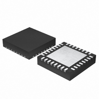
MCU 3V 16K 32-QFN
Manufacturer
Renesas Electronics America
Series
H8® H8/300H SLPr
Datasheet
1.DF38602RFT10.pdf
(554 pages)
Specifications of DF38602RFT10
Core Processor
H8/300H
Core Size
16-Bit
Speed
10MHz
Connectivity
I²C, IrDA, SCI, SSU
Peripherals
POR, PWM, WDT
Number Of I /o
13
Program Memory Size
16KB (16K x 8)
Program Memory Type
FLASH
Ram Size
1K x 8
Voltage - Supply (vcc/vdd)
2.7 V ~ 3.6 V
Data Converters
A/D 6x10b
Oscillator Type
Internal
Operating Temperature
-20°C ~ 75°C
Package / Case
32-QFN
Lead Free Status / RoHS Status
Contains lead / RoHS non-compliant
Eeprom Size
-
Other names
HD64F38602RFT10
HD64F38602RFT10
HD64F38602RFT10
Available stocks
Company
Part Number
Manufacturer
Quantity
Price
Company:

Part Number:
DF38602RFT10V
Manufacturer:
Renesas Electronics America
Quantity:
135


Section 19 Power-On Reset Circuit
19.2
19.2.1
The operation timing of the power-on reset circuit is shown in figure 19.2. As the power supply
voltage rises, the capacitor, which is externally connected to the RES pin, is gradually charged
through the on-chip pull-up resistor (Rp). The low level of the RES pin is sent to the LSI and the
whole LSI is reset. When the level of the RES pin reaches to the predetermined level, a voltage
detection circuit detects it. Then a 3-bit counter starts counting up. When the 3-bit counter counts
φ for 8 times, an overflow signal is generated and an internal reset signal is negated.
The capacitance (C
formula; where the RES rising time is t. For the on-chip resistor (Rp), see section 21, Electrical
Characteristics. The power supply rising time (t_vtr) should be shorter than half the RES rising
time (t). The RES rising time (t) is also should be longer than the oscillation stabilization time
(trc).
Note that the power supply voltage (Vcc) must fall below Vpor = 100 mV and rise after charge on
the RES pin is removed. To remove charge on the RES pin, it is recommended that the diode
should be placed near Vcc. If the power supply voltage (Vcc) rises from the point above Vpor, a
power-on reset may not occur.
Rev. 3.00 May 15, 2007 Page 370 of 516
REJ09B0152-0300
Internal reset
signal
C
Vcc
RES
Operation
RES
Power-On Reset Circuit
=
RES
Figure 19.2 Power-On Reset Circuit Operation Timing
Rp
t
) which is connected to the RES pin can be computed using the following
(t > trc, t > t_vtr × 2)
t_vtr
t_vtr × 2
V_rst
t_cr
t_out (eight states)
Related parts for DF38602RFT10
Image
Part Number
Description
Manufacturer
Datasheet
Request
R

Part Number:
Description:
KIT STARTER FOR M16C/29
Manufacturer:
Renesas Electronics America
Datasheet:

Part Number:
Description:
KIT STARTER FOR R8C/2D
Manufacturer:
Renesas Electronics America
Datasheet:

Part Number:
Description:
R0K33062P STARTER KIT
Manufacturer:
Renesas Electronics America
Datasheet:

Part Number:
Description:
KIT STARTER FOR R8C/23 E8A
Manufacturer:
Renesas Electronics America
Datasheet:

Part Number:
Description:
KIT STARTER FOR R8C/25
Manufacturer:
Renesas Electronics America
Datasheet:

Part Number:
Description:
KIT STARTER H8S2456 SHARPE DSPLY
Manufacturer:
Renesas Electronics America
Datasheet:

Part Number:
Description:
KIT STARTER FOR R8C38C
Manufacturer:
Renesas Electronics America
Datasheet:

Part Number:
Description:
KIT STARTER FOR R8C35C
Manufacturer:
Renesas Electronics America
Datasheet:

Part Number:
Description:
KIT STARTER FOR R8CL3AC+LCD APPS
Manufacturer:
Renesas Electronics America
Datasheet:
Part Number:
Description:
KIT STARTER FOR RX610
Manufacturer:
Renesas Electronics America
Datasheet:

Part Number:
Description:
KIT STARTER FOR R32C/118
Manufacturer:
Renesas Electronics America
Datasheet:

Part Number:
Description:
KIT DEV RSK-R8C/26-29
Manufacturer:
Renesas Electronics America
Datasheet:

Part Number:
Description:
KIT STARTER FOR SH7124
Manufacturer:
Renesas Electronics America
Datasheet:

Part Number:
Description:
KIT STARTER FOR H8SX/1622
Manufacturer:
Renesas Electronics America
Datasheet:

Part Number:
Description:
KIT DEV FOR SH7203
Manufacturer:
Renesas Electronics America
Datasheet: