DF38602RFT10 Renesas Electronics America, DF38602RFT10 Datasheet - Page 244
DF38602RFT10
Manufacturer Part Number
DF38602RFT10
Description
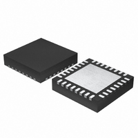
MCU 3V 16K 32-QFN
Manufacturer
Renesas Electronics America
Series
H8® H8/300H SLPr
Datasheet
1.DF38602RFT10.pdf
(554 pages)
Specifications of DF38602RFT10
Core Processor
H8/300H
Core Size
16-Bit
Speed
10MHz
Connectivity
I²C, IrDA, SCI, SSU
Peripherals
POR, PWM, WDT
Number Of I /o
13
Program Memory Size
16KB (16K x 8)
Program Memory Type
FLASH
Ram Size
1K x 8
Voltage - Supply (vcc/vdd)
2.7 V ~ 3.6 V
Data Converters
A/D 6x10b
Oscillator Type
Internal
Operating Temperature
-20°C ~ 75°C
Package / Case
32-QFN
Lead Free Status / RoHS Status
Contains lead / RoHS non-compliant
Eeprom Size
-
Other names
HD64F38602RFT10
HD64F38602RFT10
HD64F38602RFT10
Available stocks
Company
Part Number
Manufacturer
Quantity
Price
Company:

Part Number:
DF38602RFT10V
Manufacturer:
Renesas Electronics America
Quantity:
135


Section 12 Watchdog Timer
12.4
During interval timer mode operation, an overflow generates an interval timer interrupt. The
interval timer interrupt is requested whenever the OVF flag is set to 1 in TCSRWD2. The OVF
flag must be cleared to 0 in the interrupt handling routine.
12.5
12.5.1
If modes are switched between watchdog timer and interval timer, while the WDT is operating, an
error may occur in the count value. Software must stop the watchdog timer (by clearing the
WDON bit to 0) before switching modes.
12.5.2
The WDCKSTP bit in CKSTPR2 is valid when the WDON bit in the timer control/status register
WD1 (TCSRWD1) is cleared to 0. The WDCKSTP bit can be cleared to 0 while the WDON bit is
set to 1 (while the watchdog timer is operating). However, the watchdog timer does not enter
module standby mode but continues operating. When the WDON bit is cleared to 0 by software
after the watchdog timer stops operating, the WDCKSTP bit is valid at the same time and the
watchdog timer enters module standby mode.
12.5.3
When clearing the WT/IT or IEOVF bit in the timer control/status register WD2 (TCSRWD2) to
0, the corresponding bit may not be cleared to 0 depending on the program address. In particular,
if lower two bits in the address of the MOV.B instruction to transfer a value to TCSRWD2 are
B'10, the WT/IT or IEOVF bit is successfully cleared to 0, whereas if lower two bits in the address
are B'00, the WT/IT or IEOVF bit may not be cleared to 0. To avoid this failure, make sure to use
the assembly program shown in table 12.1, when clearing the WT/IT or IEOVF bit to 0. Specify
TCSRWD2 by the 8-bit absolute address, and LABEL by the 16-bit absolute address. Don't
change nor add instructions. The value of "xx" in line 1 and line 4 must be set according to table
12.2. Use an arbitrary 8-bit general register for Rn and Rm. In addition, Address1 in table 12.1
shows an example when the WT/IT or IEOVF bit is cleared to 0 successfully by the MOV.B
instruction in line 2. Address2 in table 12.1 shows an example when the WT/IT or IEOVF bit fails
to be cleared to 0 by the MOV.B instruction in line 2, but cleared to 0 by the MOV.B instruction
in line 6.
Rev. 3.00 May 15, 2007 Page 210 of 516
REJ09B0152-0300
Switching between Watchdog Timer Mode and Interval Timer Mode
Module Standby Mode Control
Clearing the WT/IT or IEOVF Bit in TCSRWD2 to 0
Interrupt
Usage Notes
Related parts for DF38602RFT10
Image
Part Number
Description
Manufacturer
Datasheet
Request
R

Part Number:
Description:
KIT STARTER FOR M16C/29
Manufacturer:
Renesas Electronics America
Datasheet:

Part Number:
Description:
KIT STARTER FOR R8C/2D
Manufacturer:
Renesas Electronics America
Datasheet:

Part Number:
Description:
R0K33062P STARTER KIT
Manufacturer:
Renesas Electronics America
Datasheet:

Part Number:
Description:
KIT STARTER FOR R8C/23 E8A
Manufacturer:
Renesas Electronics America
Datasheet:

Part Number:
Description:
KIT STARTER FOR R8C/25
Manufacturer:
Renesas Electronics America
Datasheet:

Part Number:
Description:
KIT STARTER H8S2456 SHARPE DSPLY
Manufacturer:
Renesas Electronics America
Datasheet:

Part Number:
Description:
KIT STARTER FOR R8C38C
Manufacturer:
Renesas Electronics America
Datasheet:

Part Number:
Description:
KIT STARTER FOR R8C35C
Manufacturer:
Renesas Electronics America
Datasheet:

Part Number:
Description:
KIT STARTER FOR R8CL3AC+LCD APPS
Manufacturer:
Renesas Electronics America
Datasheet:
Part Number:
Description:
KIT STARTER FOR RX610
Manufacturer:
Renesas Electronics America
Datasheet:

Part Number:
Description:
KIT STARTER FOR R32C/118
Manufacturer:
Renesas Electronics America
Datasheet:

Part Number:
Description:
KIT DEV RSK-R8C/26-29
Manufacturer:
Renesas Electronics America
Datasheet:

Part Number:
Description:
KIT STARTER FOR SH7124
Manufacturer:
Renesas Electronics America
Datasheet:

Part Number:
Description:
KIT STARTER FOR H8SX/1622
Manufacturer:
Renesas Electronics America
Datasheet:

Part Number:
Description:
KIT DEV FOR SH7203
Manufacturer:
Renesas Electronics America
Datasheet: