DF38602RFT10 Renesas Electronics America, DF38602RFT10 Datasheet - Page 381
DF38602RFT10
Manufacturer Part Number
DF38602RFT10
Description
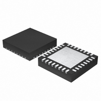
MCU 3V 16K 32-QFN
Manufacturer
Renesas Electronics America
Series
H8® H8/300H SLPr
Datasheet
1.DF38602RFT10.pdf
(554 pages)
Specifications of DF38602RFT10
Core Processor
H8/300H
Core Size
16-Bit
Speed
10MHz
Connectivity
I²C, IrDA, SCI, SSU
Peripherals
POR, PWM, WDT
Number Of I /o
13
Program Memory Size
16KB (16K x 8)
Program Memory Type
FLASH
Ram Size
1K x 8
Voltage - Supply (vcc/vdd)
2.7 V ~ 3.6 V
Data Converters
A/D 6x10b
Oscillator Type
Internal
Operating Temperature
-20°C ~ 75°C
Package / Case
32-QFN
Lead Free Status / RoHS Status
Contains lead / RoHS non-compliant
Eeprom Size
-
Other names
HD64F38602RFT10
HD64F38602RFT10
HD64F38602RFT10
Available stocks
Company
Part Number
Manufacturer
Quantity
Price
Company:

Part Number:
DF38602RFT10V
Manufacturer:
Renesas Electronics America
Quantity:
135


16.7
16.7.1
The stop condition or start (re-transmit) condition should be issued after recognizing the falling
edge of the ninth clock. The falling edge of the ninth clock can be recognized by checking the
SCLO bit in the I2C control register 2 (ICCR2). Note that if the stop condition or start (re-
transmit) condition is issued in a particular timing and the situations shown below, these
conditions may not correctly output.
1. The rising edge of the SCL becomes less sharp and longer due to the SCL bus load (load
2. When the slave device elongates the low level period between the eighth and ninth clocks and
16.7.2
The WAIT bit in the I
set to 1, when a slave device holds the SCL signal low more than one transfer clock cycle during
the eighth clock, the high level period of the ninth clock may be shorter than a given period.
16.7.3
In multimaster operation, if the IIC transfer rate setting in this LSI is slower than those of the other
masters, SCL may be output with an unexpected width. To avoid this phenomenon, set the transfer
rate by 1/1.8 or faster than the fastest rate of the other masters. For example, if the fastest transfer
rate of the other masters is set to 400 kbps, the IIC transfer rate in this LSI should be set to 223
kbps (= 400/1.18) or more.
capacitor and pull-up resistor) than the period defined in section 16.6, Bit Synchronous Circuit.
activates the bit synchronous circuit.
Usage Notes
Note on Issuing Stop Condition and Start (Re-Transmit) Condition
Note on Setting WAIT Bit in I2C Bus Mode Register (ICMR)
Restriction on Transfer Rate Setting in Multimaster Operation
2
C bus mode register (ICMR) should be set to 0. Note that if the WAIT bit is
Rev. 3.00 May 15, 2007 Page 347 of 516
Section 16 I
2
C Bus Interface 2 (IIC2)
REJ09B0152-0300
Related parts for DF38602RFT10
Image
Part Number
Description
Manufacturer
Datasheet
Request
R

Part Number:
Description:
KIT STARTER FOR M16C/29
Manufacturer:
Renesas Electronics America
Datasheet:

Part Number:
Description:
KIT STARTER FOR R8C/2D
Manufacturer:
Renesas Electronics America
Datasheet:

Part Number:
Description:
R0K33062P STARTER KIT
Manufacturer:
Renesas Electronics America
Datasheet:

Part Number:
Description:
KIT STARTER FOR R8C/23 E8A
Manufacturer:
Renesas Electronics America
Datasheet:

Part Number:
Description:
KIT STARTER FOR R8C/25
Manufacturer:
Renesas Electronics America
Datasheet:

Part Number:
Description:
KIT STARTER H8S2456 SHARPE DSPLY
Manufacturer:
Renesas Electronics America
Datasheet:

Part Number:
Description:
KIT STARTER FOR R8C38C
Manufacturer:
Renesas Electronics America
Datasheet:

Part Number:
Description:
KIT STARTER FOR R8C35C
Manufacturer:
Renesas Electronics America
Datasheet:

Part Number:
Description:
KIT STARTER FOR R8CL3AC+LCD APPS
Manufacturer:
Renesas Electronics America
Datasheet:
Part Number:
Description:
KIT STARTER FOR RX610
Manufacturer:
Renesas Electronics America
Datasheet:

Part Number:
Description:
KIT STARTER FOR R32C/118
Manufacturer:
Renesas Electronics America
Datasheet:

Part Number:
Description:
KIT DEV RSK-R8C/26-29
Manufacturer:
Renesas Electronics America
Datasheet:

Part Number:
Description:
KIT STARTER FOR SH7124
Manufacturer:
Renesas Electronics America
Datasheet:

Part Number:
Description:
KIT STARTER FOR H8SX/1622
Manufacturer:
Renesas Electronics America
Datasheet:

Part Number:
Description:
KIT DEV FOR SH7203
Manufacturer:
Renesas Electronics America
Datasheet: