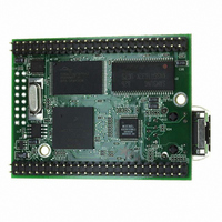
MOD5272-100IR NetBurner Inc, MOD5272-100IR Datasheet - Page 518

MOD5272-100IR
Manufacturer Part Number
MOD5272-100IR
Description
PROCESSOR MODULE FLASH MOD5272
Manufacturer
NetBurner Inc
Type
Controllers & Processorsr
Datasheets
1.MOD5272-100IR.pdf
(2 pages)
2.MOD5272-100IR.pdf
(3 pages)
3.MOD5272-100IR.pdf
(550 pages)
Specifications of MOD5272-100IR
Module/board Type
Processor Module
Ethernet Connection Type
10/100 Ethernet Port RJ-45
Operating Voltage
3.3 V
Product
Modules
Lead Free Status / RoHS Status
Lead free / RoHS Compliant
For Use With/related Products
MOD5272
For Use With
528-1001 - KIT DEVELOP NETWORK FOR MOD5272
Lead Free Status / Rohs Status
Lead free / RoHS Compliant
Other names
528-1008
- Current page: 518 of 550
- Download datasheet (6Mb)
PLIC Module: IDL and GCI Interface Timing Specifications
Figure 23-20 shows GCI master timings listed in Table 23-20.
1
2
3
4
23-24
DOUT1
DOUT3
DFSC1
DFSC2
DFSC3
Name
GDCL1_OUT
P57
P58
P59
P60
P61
DIN1
DIN3
For most telecommunications applications the period of DFSC[1:3] should be set to 125 µS. Refer to clock
generator planning in PLIC chapter.
GDCL1_OUT must be less than 1/20th of the CPU operating frequency to ensure minimum jitter to CODECs
connected to Ports 1, 2, 3.
Same as DCL0 and FSC0 if internal clock generator configured for pass-through mode.
Based on generated GDCL1_OUT less than 1/20 of CPU clock frequency.
P50
Table 23-20. GCI Master Mode Timing, PLIC PORTs 1, 2, 3 (Continued)
Delay from rising edge of GDCL1_OUT to Low-Z and valid data on
DOUT[1,3]
Delay from rising edge of GDCL1_OUT to data valid on DOUT[1,3]
Delay from rising edge of GDCL1_OUT to High-Z on DOUT[1,3]
Data valid on DIN[1:3] before rising edge of GDCL1_OUT (setup
time)
Data valid on DIN[1:3] after rising edge of GDCL1_OUT (hold time)
P57
P60
P61
Figure 23-20. GCI Master Mode Timing
Characteristic
P51
MCF5272 User’s Manual
P58
Min
25
—
—
—
25
Max
—
—
—
—
—
P59
Unit
30
30
30
—
—
P53
P52
MOTOROLA
Name
nS
nS
nS
nS
nS
P54
Related parts for MOD5272-100IR
Image
Part Number
Description
Manufacturer
Datasheet
Request
R

Part Number:
Description:
Ethernet Modules & Development Tools MOD5272 Processor Board
Manufacturer:
NetBurner Inc
Datasheet:

Part Number:
Description:
Ethernet Modules & Development Tools MOD5272 Industrial Temperature
Manufacturer:
NetBurner Inc

Part Number:
Description:
Ethernet Modules & Development Tools MOD5272 MODULE
Manufacturer:
NetBurner Inc
Datasheet:

Part Number:
Description:
PROCESSOR MODULE FLASH
Manufacturer:
NetBurner Inc
Datasheet:

Part Number:
Description:
Ethernet Modules & Development Tools 32Bit 62MHz Core Module 50Pin DIP
Manufacturer:
NetBurner Inc
Datasheet:

Part Number:
Description:
BOARD SERIAL-ETHERNET 512K FLASH
Manufacturer:
NetBurner Inc
Datasheet:

Part Number:
Description:
PROCESSOR MODULE 512KB FLASH
Manufacturer:
NetBurner Inc
Datasheet:

Part Number:
Description:
DUAL PORT SERIAL-ETHERNET
Manufacturer:
NetBurner Inc
Datasheet:

Part Number:
Description:
PROCESSOR MODULE 512KB FLASH
Manufacturer:
NetBurner Inc
Datasheet:

Part Number:
Description:
MOD5234 10/100 ETHERNET MODULE
Manufacturer:
NetBurner Inc
Datasheet:

Part Number:
Description:
KIT DEVELOP NETWORK FOR MOD5282
Manufacturer:
NetBurner Inc
Datasheet:

Part Number:
Description:
KIT DEVELOP NETWORK FOR MOD5272
Manufacturer:
NetBurner Inc
Datasheet:

Part Number:
Description:
Ethernet ICs 32bit 147MHz CAN-to- Ethnt Device IndTemp
Manufacturer:
NetBurner Inc
Datasheet:


