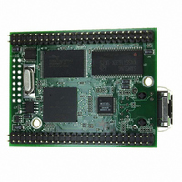
MOD5272-100IR NetBurner Inc, MOD5272-100IR Datasheet - Page 436

MOD5272-100IR
Manufacturer Part Number
MOD5272-100IR
Description
PROCESSOR MODULE FLASH MOD5272
Manufacturer
NetBurner Inc
Type
Controllers & Processorsr
Datasheets
1.MOD5272-100IR.pdf
(2 pages)
2.MOD5272-100IR.pdf
(3 pages)
3.MOD5272-100IR.pdf
(550 pages)
Specifications of MOD5272-100IR
Module/board Type
Processor Module
Ethernet Connection Type
10/100 Ethernet Port RJ-45
Operating Voltage
3.3 V
Product
Modules
Lead Free Status / RoHS Status
Lead free / RoHS Compliant
For Use With/related Products
MOD5272
For Use With
528-1001 - KIT DEVELOP NETWORK FOR MOD5272
Lead Free Status / Rohs Status
Lead free / RoHS Compliant
Other names
528-1008
- Current page: 436 of 550
- Download datasheet (6Mb)
CPU Clock and Reset Signals
19.6.6 Bypass
Bypass is a Motorola test mode signal. This signal should be left unconnected.
19.6.7 SDRAM Row Address Strobe (RAS0)
RAS0 is the SDRAM row address strobe output.
19.6.8 SDRAM Column Address Strobe (CAS0)
CAS0 is the SDRAM column address strobe output.
19.6.9 SDRAM Clock (SDCLK)
The SDRAM clock output (SDCLK) is the same frequency as the CPU clock.
19.6.10 SDRAM Write Enable (SDWE)
This output is the SDRAM write enable.
19.6.11 SDRAM Clock Enable (SDCLKE)
This output is the SDRAM clock enable.
19.6.12 SDRAM Bank Selects (SDBA[1:0])
These outputs are the SDRAM bank select signals.
19.6.13 SDRAM Row Address 10 (A10)/A10 Precharge
(A10_PRECHG)
This output is the SDRAM row address 10 and the precharge strobe.
19.7 CPU Clock and Reset Signals
This section describes clock and reset signals in the CPU.
19.7.1 RSTI
RSTI is the primary reset input to the device. Asserting RSTI immediately resets the CPU
and peripherals. However, the reset of the SDRAM controller and hence SDRAM contents
depend on DRESETEN. Asserting RSTI also causes RSTO to be asserted for 32K CPU
clock cycles.
19-22
MCF5272 User’s Manual
MOTOROLA
Related parts for MOD5272-100IR
Image
Part Number
Description
Manufacturer
Datasheet
Request
R

Part Number:
Description:
Ethernet Modules & Development Tools MOD5272 Processor Board
Manufacturer:
NetBurner Inc
Datasheet:

Part Number:
Description:
Ethernet Modules & Development Tools MOD5272 Industrial Temperature
Manufacturer:
NetBurner Inc

Part Number:
Description:
Ethernet Modules & Development Tools MOD5272 MODULE
Manufacturer:
NetBurner Inc
Datasheet:

Part Number:
Description:
PROCESSOR MODULE FLASH
Manufacturer:
NetBurner Inc
Datasheet:

Part Number:
Description:
Ethernet Modules & Development Tools 32Bit 62MHz Core Module 50Pin DIP
Manufacturer:
NetBurner Inc
Datasheet:

Part Number:
Description:
BOARD SERIAL-ETHERNET 512K FLASH
Manufacturer:
NetBurner Inc
Datasheet:

Part Number:
Description:
PROCESSOR MODULE 512KB FLASH
Manufacturer:
NetBurner Inc
Datasheet:

Part Number:
Description:
DUAL PORT SERIAL-ETHERNET
Manufacturer:
NetBurner Inc
Datasheet:

Part Number:
Description:
PROCESSOR MODULE 512KB FLASH
Manufacturer:
NetBurner Inc
Datasheet:

Part Number:
Description:
MOD5234 10/100 ETHERNET MODULE
Manufacturer:
NetBurner Inc
Datasheet:

Part Number:
Description:
KIT DEVELOP NETWORK FOR MOD5282
Manufacturer:
NetBurner Inc
Datasheet:

Part Number:
Description:
KIT DEVELOP NETWORK FOR MOD5272
Manufacturer:
NetBurner Inc
Datasheet:

Part Number:
Description:
Ethernet ICs 32bit 147MHz CAN-to- Ethnt Device IndTemp
Manufacturer:
NetBurner Inc
Datasheet:


