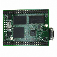
MOD5272-100IR NetBurner Inc, MOD5272-100IR Datasheet - Page 298

MOD5272-100IR
Manufacturer Part Number
MOD5272-100IR
Description
PROCESSOR MODULE FLASH MOD5272
Manufacturer
NetBurner Inc
Type
Controllers & Processorsr
Datasheets
1.MOD5272-100IR.pdf
(2 pages)
2.MOD5272-100IR.pdf
(3 pages)
3.MOD5272-100IR.pdf
(550 pages)
Specifications of MOD5272-100IR
Module/board Type
Processor Module
Ethernet Connection Type
10/100 Ethernet Port RJ-45
Operating Voltage
3.3 V
Product
Modules
Lead Free Status / RoHS Status
Lead free / RoHS Compliant
For Use With/related Products
MOD5272
For Use With
528-1001 - KIT DEVELOP NETWORK FOR MOD5272
Lead Free Status / Rohs Status
Lead free / RoHS Compliant
Other names
528-1008
- Current page: 298 of 550
- Download datasheet (6Mb)
Introduction
through set 1. port 3 can use either pin set 1 or 3. Pin set 3 consists of data in and data out.
Data clock and frame sync are common to pin set 1 and 3. In the case of set 1, which
connects multiple ports, separate delayed frame sync generators are provided for each port
which distinguish each port’s active time slots. See Section 13.6, “Application Examples”
for further information.
Figure 13-1 illustrates the basic PLIC system.
The four ports have the following timing and connectivity features:
13-2
DCL0/URT1_CLK, DIN0/URT1_RxD,
DOUT0/URT1_TxD, PA10/DREQ0
• Port 0: Connects through pin set 0. Operates as a slave-only port; that is, an external
• Port 1: Connects through pin set 1. Operates as a master or slave port. In slave mode
PA8/FSC0/FSR0, PA9/DGNT0,
device must source frame sync clock/frame sync receive (FSC/FSR) and data clock
(DCL). These pins are unidirectional inputs. Din0 and Dout0 are dedicated pins for
port 0.
an external device must source FSC/FSR and DCL. In master mode, DCL1 and
FSC1/FSR1 are outputs. These signals are in turn derived from the DCL0 and
FSC/FSR from port 0. For port 1 to function in master mode, port 0 must be enabled
with an external transceiver sourcing DCL and FSC/FSR. The physical interface
pins Din1 and Dout1 serve ports 1, 2, and 3.
GCI/IDL
Pin Set 0
Port 0
32
Figure 13-1. PLIC System Diagram
Generator
Timing
Internal Interface Registers
MCF5272 User’s Manual
PA15_INT6/DGNT1_INT6, DOUT1, DIN1
Internal Bus
Timing
Gen
DCL1/GDCL1_OUT, PA14,
GCI/IDL
Port 1
FSC1/FSR1/DFSC1,
32
Pin Set 1
Pin Set 1 Mux
GCI/IDL
Port 2
Timing
Gen
32
PA7/QSPI_CS3/DOUT3,
Pin Set 3
GCI/IDL
Port 3
Mux
DIN3/INT4
Pin Set 3
32
DIN3
DOUT
MOTOROLA
Timing
Gen
Related parts for MOD5272-100IR
Image
Part Number
Description
Manufacturer
Datasheet
Request
R

Part Number:
Description:
Ethernet Modules & Development Tools MOD5272 Processor Board
Manufacturer:
NetBurner Inc
Datasheet:

Part Number:
Description:
Ethernet Modules & Development Tools MOD5272 Industrial Temperature
Manufacturer:
NetBurner Inc

Part Number:
Description:
Ethernet Modules & Development Tools MOD5272 MODULE
Manufacturer:
NetBurner Inc
Datasheet:

Part Number:
Description:
PROCESSOR MODULE FLASH
Manufacturer:
NetBurner Inc
Datasheet:

Part Number:
Description:
Ethernet Modules & Development Tools 32Bit 62MHz Core Module 50Pin DIP
Manufacturer:
NetBurner Inc
Datasheet:

Part Number:
Description:
BOARD SERIAL-ETHERNET 512K FLASH
Manufacturer:
NetBurner Inc
Datasheet:

Part Number:
Description:
PROCESSOR MODULE 512KB FLASH
Manufacturer:
NetBurner Inc
Datasheet:

Part Number:
Description:
DUAL PORT SERIAL-ETHERNET
Manufacturer:
NetBurner Inc
Datasheet:

Part Number:
Description:
PROCESSOR MODULE 512KB FLASH
Manufacturer:
NetBurner Inc
Datasheet:

Part Number:
Description:
MOD5234 10/100 ETHERNET MODULE
Manufacturer:
NetBurner Inc
Datasheet:

Part Number:
Description:
KIT DEVELOP NETWORK FOR MOD5282
Manufacturer:
NetBurner Inc
Datasheet:

Part Number:
Description:
KIT DEVELOP NETWORK FOR MOD5272
Manufacturer:
NetBurner Inc
Datasheet:

Part Number:
Description:
Ethernet ICs 32bit 147MHz CAN-to- Ethnt Device IndTemp
Manufacturer:
NetBurner Inc
Datasheet:


