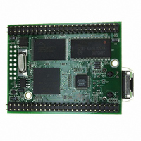
MOD5272-100IR NetBurner Inc, MOD5272-100IR Datasheet - Page 410

MOD5272-100IR
Manufacturer Part Number
MOD5272-100IR
Description
PROCESSOR MODULE FLASH MOD5272
Manufacturer
NetBurner Inc
Type
Controllers & Processorsr
Datasheets
1.MOD5272-100IR.pdf
(2 pages)
2.MOD5272-100IR.pdf
(3 pages)
3.MOD5272-100IR.pdf
(550 pages)
Specifications of MOD5272-100IR
Module/board Type
Processor Module
Ethernet Connection Type
10/100 Ethernet Port RJ-45
Operating Voltage
3.3 V
Product
Modules
Lead Free Status / RoHS Status
Lead free / RoHS Compliant
For Use With/related Products
MOD5272
For Use With
528-1001 - KIT DEVELOP NETWORK FOR MOD5272
Lead Free Status / Rohs Status
Lead free / RoHS Compliant
Other names
528-1008
- Current page: 410 of 550
- Download datasheet (6Mb)
PWM Operation
Summary of the main features include:
18.2 PWM Operation
The PWM is a simple free-running counter combined with a pulse width register and a
comparator such that the output is cleared whenever the counter value exceeds the width
register value. When the counter overflows, or “wraps around,” its value becomes less than
or equal to the value of the width register, and the output is set. With a suitable low-pass
filter, the PWM can be used as a digital-to-analog converter.
The width register is double-buffered so that a new value can be loaded for the next cycle
without affecting the current cycle. At the beginning of each period, the value of the width
buffer register is loaded into the width register, which feeds the comparator. This value is
used for comparison during the next cycle. The prescaler contains a variable divider that
can reduce the incoming clock frequency by certain values between 1 and 32768.
18.3 PWM Programming Model
This section describes the registers and control bits in the PWM module. There are three
independent PWM modules, each with its own control and width registers. The memory
map for the PWM is shown in Table 18-1.
18-2
0x00C0
0x00C4
0x00C8
0x00D0
0x00D4
0x00D8
MBAR
Offset
• Double-buffered width register
• Variable-divide prescale
• Three independent PWM modules
• Byte-wide width register provides programmable duty cycle control
PWM Pulse Width Register
PWM Pulse Width Register
PWM Pulse Width Register
PWM Control Register 0
PWM Control Register 1
PWM Control Register 2
0 (PWWD0), [p. 18-4]
1 (PWWD1), [p. 18-4]
2 (PWWD2), [p. 18-4]
(PWCR0), [p. 18-3]
(PWCR1), [p. 18-3]
(PWCR2), [p. 18-3]
[31:24]
Table 18-1. PWM Module Memory Map
MCF5272 User’s Manual
[23:16]
Reserved
Reserved
Reserved
Reserved
Reserved
Reserved
[15:8]
[7:0]
MOTOROLA
Related parts for MOD5272-100IR
Image
Part Number
Description
Manufacturer
Datasheet
Request
R

Part Number:
Description:
Ethernet Modules & Development Tools MOD5272 Processor Board
Manufacturer:
NetBurner Inc
Datasheet:

Part Number:
Description:
Ethernet Modules & Development Tools MOD5272 Industrial Temperature
Manufacturer:
NetBurner Inc

Part Number:
Description:
Ethernet Modules & Development Tools MOD5272 MODULE
Manufacturer:
NetBurner Inc
Datasheet:

Part Number:
Description:
PROCESSOR MODULE FLASH
Manufacturer:
NetBurner Inc
Datasheet:

Part Number:
Description:
Ethernet Modules & Development Tools 32Bit 62MHz Core Module 50Pin DIP
Manufacturer:
NetBurner Inc
Datasheet:

Part Number:
Description:
BOARD SERIAL-ETHERNET 512K FLASH
Manufacturer:
NetBurner Inc
Datasheet:

Part Number:
Description:
PROCESSOR MODULE 512KB FLASH
Manufacturer:
NetBurner Inc
Datasheet:

Part Number:
Description:
DUAL PORT SERIAL-ETHERNET
Manufacturer:
NetBurner Inc
Datasheet:

Part Number:
Description:
PROCESSOR MODULE 512KB FLASH
Manufacturer:
NetBurner Inc
Datasheet:

Part Number:
Description:
MOD5234 10/100 ETHERNET MODULE
Manufacturer:
NetBurner Inc
Datasheet:

Part Number:
Description:
KIT DEVELOP NETWORK FOR MOD5282
Manufacturer:
NetBurner Inc
Datasheet:

Part Number:
Description:
KIT DEVELOP NETWORK FOR MOD5272
Manufacturer:
NetBurner Inc
Datasheet:

Part Number:
Description:
Ethernet ICs 32bit 147MHz CAN-to- Ethnt Device IndTemp
Manufacturer:
NetBurner Inc
Datasheet:


