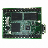
MOD5272-100IR NetBurner Inc, MOD5272-100IR Datasheet - Page 256

MOD5272-100IR
Manufacturer Part Number
MOD5272-100IR
Description
PROCESSOR MODULE FLASH MOD5272
Manufacturer
NetBurner Inc
Type
Controllers & Processorsr
Datasheets
1.MOD5272-100IR.pdf
(2 pages)
2.MOD5272-100IR.pdf
(3 pages)
3.MOD5272-100IR.pdf
(550 pages)
Specifications of MOD5272-100IR
Module/board Type
Processor Module
Ethernet Connection Type
10/100 Ethernet Port RJ-45
Operating Voltage
3.3 V
Product
Modules
Lead Free Status / RoHS Status
Lead free / RoHS Compliant
For Use With/related Products
MOD5272
For Use With
528-1001 - KIT DEVELOP NETWORK FOR MOD5272
Lead Free Status / Rohs Status
Lead free / RoHS Compliant
Other names
528-1008
- Current page: 256 of 550
- Download datasheet (6Mb)
Buffer Descriptors
11.6 Buffer Descriptors
Data associated with the FEC controller is stored in buffers, which are referenced by buffer
descriptors (BDs) organized as tables in the dual-port RAM. These tables have the same
basic configuration as those used by the USB.
The BD table allows users to define separate buffers for transmission and reception. Each
table forms a circular queue, or ring. The FEC uses status and control fields in the BDs to
inform the core that the buffers have been serviced, to confirm reception and transmission
events, or to indicate error conditions.
11.6.1 FEC Buffer Descriptor Tables
The data for the fast Ethernet frames must reside in memory external to the FEC. The data
for a frame is placed in one or more buffers. Each buffer has a pointer to it in a buffer
descriptor (BD). In addition to pointing to the buffer, the BD contains the current state of
the buffer. To permit maximum user flexibility, the BDs are also located in external
memory.
Software defines buffers by allocating/initializing memory and initializing buffer
descriptors. Setting the RxBD[E] or TxBD[R] produces the buffer. Software writing to
either TDAR or RDAR tells the FEC that a buffer has been placed in external memory for
the transmit or receive data traffic, respectively. The hardware reads the BDs and processes
the buffers after they have been defined. After the data DMA is complete and the BDs have
been written by the DMA engine, RxBD[E] or TxBD[R] are cleared by hardware to
indicate that the buffer has been processed. Software may poll the BDs to detect when the
buffers have been processed or may rely on the buffer/frame interrupts.
The ETHER_EN signal operates as a reset to the BD/DMA logic. When ETHER_EN is
negated, the DMA engine BD pointers are reset to point to the starting transmit and receive
BDs. The buffer descriptors are not initialized by hardware during reset. At least one
transmit and receive BD must be initialized by software (write 0x0000_0000 to the most
significant word of buffer descriptor) before the ETHER_EN bit is set.
The BDs are organized in two separate rings, one for receive buffers and one for transmit
buffers. ERDSR defines the starting address of the receive BDs and ETDSR the same for
the transmit BDs. The last buffer descriptor in each ring is defined by the wrap (W) bit.
When set, W indicates that the next descriptor in the ring is at the location pointed to by
ERDSR and ETDSR for the receive and transmit rings, respectively. Buffers descriptor
rings must start on a double-word boundary.
The format of the transmit and receive buffer descriptors are given in Figure 11-26 and
Figure 11-27.
11-32
MCF5272 User’s Manual
MOTOROLA
Related parts for MOD5272-100IR
Image
Part Number
Description
Manufacturer
Datasheet
Request
R

Part Number:
Description:
Ethernet Modules & Development Tools MOD5272 Processor Board
Manufacturer:
NetBurner Inc
Datasheet:

Part Number:
Description:
Ethernet Modules & Development Tools MOD5272 Industrial Temperature
Manufacturer:
NetBurner Inc

Part Number:
Description:
Ethernet Modules & Development Tools MOD5272 MODULE
Manufacturer:
NetBurner Inc
Datasheet:

Part Number:
Description:
PROCESSOR MODULE FLASH
Manufacturer:
NetBurner Inc
Datasheet:

Part Number:
Description:
Ethernet Modules & Development Tools 32Bit 62MHz Core Module 50Pin DIP
Manufacturer:
NetBurner Inc
Datasheet:

Part Number:
Description:
BOARD SERIAL-ETHERNET 512K FLASH
Manufacturer:
NetBurner Inc
Datasheet:

Part Number:
Description:
PROCESSOR MODULE 512KB FLASH
Manufacturer:
NetBurner Inc
Datasheet:

Part Number:
Description:
DUAL PORT SERIAL-ETHERNET
Manufacturer:
NetBurner Inc
Datasheet:

Part Number:
Description:
PROCESSOR MODULE 512KB FLASH
Manufacturer:
NetBurner Inc
Datasheet:

Part Number:
Description:
MOD5234 10/100 ETHERNET MODULE
Manufacturer:
NetBurner Inc
Datasheet:

Part Number:
Description:
KIT DEVELOP NETWORK FOR MOD5282
Manufacturer:
NetBurner Inc
Datasheet:

Part Number:
Description:
KIT DEVELOP NETWORK FOR MOD5272
Manufacturer:
NetBurner Inc
Datasheet:

Part Number:
Description:
Ethernet ICs 32bit 147MHz CAN-to- Ethnt Device IndTemp
Manufacturer:
NetBurner Inc
Datasheet:


