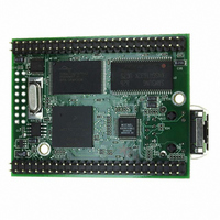
MOD5272-100IR NetBurner Inc, MOD5272-100IR Datasheet - Page 307

MOD5272-100IR
Manufacturer Part Number
MOD5272-100IR
Description
PROCESSOR MODULE FLASH MOD5272
Manufacturer
NetBurner Inc
Type
Controllers & Processorsr
Datasheets
1.MOD5272-100IR.pdf
(2 pages)
2.MOD5272-100IR.pdf
(3 pages)
3.MOD5272-100IR.pdf
(550 pages)
Specifications of MOD5272-100IR
Module/board Type
Processor Module
Ethernet Connection Type
10/100 Ethernet Port RJ-45
Operating Voltage
3.3 V
Product
Modules
Lead Free Status / RoHS Status
Lead free / RoHS Compliant
For Use With/related Products
MOD5272
For Use With
528-1001 - KIT DEVELOP NETWORK FOR MOD5272
Lead Free Status / Rohs Status
Lead free / RoHS Compliant
Other names
528-1008
- Current page: 307 of 550
- Download datasheet (6Mb)
MOTOROLA
13.2.5.3 Interrupt Control
There are a number of control mechanisms for the periodic and aperiodic interrupts on the
PLIC.
13.3 PLIC Timing Generator
13.3.1 Clock Synthesis
The PLIC clock generator employs a completely digital, synchronous design which can be
used to synthesize a new clock by multiplying an incoming reference clock. This clock
generator is not a PLL—it has no VCO or phase comparator.
The frequency multiplication factor is always an integral power of two between 2 and 256
inclusive. The amount of phase jitter exhibited by the synthesized clock increases as the
synthesized clock frequency approaches CLKIN’s frequency. As a general guide, the
maximum generated DCL should be no greater than one-twentieth of CLKIN’s frequency.
Therefore, given a CLKIN of 66 MHz, the maximum frequency which can be synthesized
with acceptable jitter is approximately 3.3 MHz.
• Monitor channel receive: ASR defines which port or ports have generated a monitor
• Monitor channel transmit: ASR defines which port or ports have generated a monitor
• C/I channel receive: ASR defines which port or ports have generated a C/I channel
• C/I channel transmit: ASR defines which port or ports have generated a C/I channel
• Clearing the ON/OFF bit in the port configuration register, Section 13.5.7, “Port
• Clearing the enable bits, ENB1 or ENB2, in the port configuration register masks the
• Specific interrupt enables are provided in each port’s ICR. This includes a port
channel receive interrupt. The interrupt service routine must then read the
appropriate GMR register or registers to clear the monitor channel receive interrupt.
channel transmit interrupt. The interrupt service routine must then read the
appropriate GMT register or registers to clear the monitor channel transmit interrupt.
receive interrupt. The interrupt service routine must then read the appropriate GCIR
register or registers to clear the C/I channel receive interrupt.
transmit interrupt. The interrupt service routine must then read the appropriate GCIT
register or registers to clear the C/I channel transmit interrupt.
Configuration Registers (P0CR–P3CR),” turns the port off and masks all periodic
and aperiodic interrupts for the affected port.
periodic transmit and receive interrupts associated with the respective B1 or B2
channel.
interrupt enable, IE, which masks all periodic and aperiodic interrupts. In addition,
there are interrupt enables for specific conditions. These are listed in Section 13.5.9,
“Interrupt Configuration Registers (P0ICR–P3ICR).”
Chapter 13. Physical Layer Interface Controller (PLIC)
PLIC Timing Generator
13-11
Related parts for MOD5272-100IR
Image
Part Number
Description
Manufacturer
Datasheet
Request
R

Part Number:
Description:
Ethernet Modules & Development Tools MOD5272 Processor Board
Manufacturer:
NetBurner Inc
Datasheet:

Part Number:
Description:
Ethernet Modules & Development Tools MOD5272 Industrial Temperature
Manufacturer:
NetBurner Inc

Part Number:
Description:
Ethernet Modules & Development Tools MOD5272 MODULE
Manufacturer:
NetBurner Inc
Datasheet:

Part Number:
Description:
PROCESSOR MODULE FLASH
Manufacturer:
NetBurner Inc
Datasheet:

Part Number:
Description:
Ethernet Modules & Development Tools 32Bit 62MHz Core Module 50Pin DIP
Manufacturer:
NetBurner Inc
Datasheet:

Part Number:
Description:
BOARD SERIAL-ETHERNET 512K FLASH
Manufacturer:
NetBurner Inc
Datasheet:

Part Number:
Description:
PROCESSOR MODULE 512KB FLASH
Manufacturer:
NetBurner Inc
Datasheet:

Part Number:
Description:
DUAL PORT SERIAL-ETHERNET
Manufacturer:
NetBurner Inc
Datasheet:

Part Number:
Description:
PROCESSOR MODULE 512KB FLASH
Manufacturer:
NetBurner Inc
Datasheet:

Part Number:
Description:
MOD5234 10/100 ETHERNET MODULE
Manufacturer:
NetBurner Inc
Datasheet:

Part Number:
Description:
KIT DEVELOP NETWORK FOR MOD5282
Manufacturer:
NetBurner Inc
Datasheet:

Part Number:
Description:
KIT DEVELOP NETWORK FOR MOD5272
Manufacturer:
NetBurner Inc
Datasheet:

Part Number:
Description:
Ethernet ICs 32bit 147MHz CAN-to- Ethnt Device IndTemp
Manufacturer:
NetBurner Inc
Datasheet:


