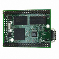
MOD5272-100IR NetBurner Inc, MOD5272-100IR Datasheet - Page 336

MOD5272-100IR
Manufacturer Part Number
MOD5272-100IR
Description
PROCESSOR MODULE FLASH MOD5272
Manufacturer
NetBurner Inc
Type
Controllers & Processorsr
Datasheets
1.MOD5272-100IR.pdf
(2 pages)
2.MOD5272-100IR.pdf
(3 pages)
3.MOD5272-100IR.pdf
(550 pages)
Specifications of MOD5272-100IR
Module/board Type
Processor Module
Ethernet Connection Type
10/100 Ethernet Port RJ-45
Operating Voltage
3.3 V
Product
Modules
Lead Free Status / RoHS Status
Lead free / RoHS Compliant
For Use With/related Products
MOD5272
For Use With
528-1001 - KIT DEVELOP NETWORK FOR MOD5272
Lead Free Status / Rohs Status
Lead free / RoHS Compliant
Other names
528-1008
- Current page: 336 of 550
- Download datasheet (6Mb)
DFSC2
DFSC3
Application Examples
Figure 13-40 shows the IDL bus timing relationship of the CODECs and U transceiver
when in standard IDL2 10-bit mode with a common frame sync.
Dout1
In the above example, CODEC 1 transmits and receives in the B3 time slot once the
U transceiver has completed the D channel. From the rising edge of FSC1, this is at least
19 DCL clocks later. In Figure 13-40, a short, optional delay, is shown between the end of
the D channel and the start of the B3 channel. For example, let us say this is 1 DCL clocks
long. This defines the programmable delay 1 value to be 20, (19 + 1), or 0x0014. The
DFSC3 signal synchronizes CODECs 3 and 4, and the rising edge of this frame sync occurs
20 clocks after DFSC2, therefore 40 DCL clocks after FSC1. This defines the value for
programmable delay 3 to be 40, (19 + 1 + 20), or 0x0028.
13.6.5 Example 3: Two-Line Remote Access with Ports 0
In this example, ports 0 and 1 are connected to two S/T transceivers. Ports 0 and 1 are
programmed in slave mode. Ports 2 and 3 are not used, and may be disabled.
FSC1
13-40
Din1/
DCL
and 1
B1
U Transceiver
D
Figure 13-40. Standard IDL2 10-bit mode.
B2
D
MCF5272 User’s Manual
CODEC 1
B3
CODEC 2
B4
CODEC 3
B5
CODEC 4
MOTOROLA
B6
Related parts for MOD5272-100IR
Image
Part Number
Description
Manufacturer
Datasheet
Request
R

Part Number:
Description:
Ethernet Modules & Development Tools MOD5272 Processor Board
Manufacturer:
NetBurner Inc
Datasheet:

Part Number:
Description:
Ethernet Modules & Development Tools MOD5272 Industrial Temperature
Manufacturer:
NetBurner Inc

Part Number:
Description:
Ethernet Modules & Development Tools MOD5272 MODULE
Manufacturer:
NetBurner Inc
Datasheet:

Part Number:
Description:
PROCESSOR MODULE FLASH
Manufacturer:
NetBurner Inc
Datasheet:

Part Number:
Description:
Ethernet Modules & Development Tools 32Bit 62MHz Core Module 50Pin DIP
Manufacturer:
NetBurner Inc
Datasheet:

Part Number:
Description:
BOARD SERIAL-ETHERNET 512K FLASH
Manufacturer:
NetBurner Inc
Datasheet:

Part Number:
Description:
PROCESSOR MODULE 512KB FLASH
Manufacturer:
NetBurner Inc
Datasheet:

Part Number:
Description:
DUAL PORT SERIAL-ETHERNET
Manufacturer:
NetBurner Inc
Datasheet:

Part Number:
Description:
PROCESSOR MODULE 512KB FLASH
Manufacturer:
NetBurner Inc
Datasheet:

Part Number:
Description:
MOD5234 10/100 ETHERNET MODULE
Manufacturer:
NetBurner Inc
Datasheet:

Part Number:
Description:
KIT DEVELOP NETWORK FOR MOD5282
Manufacturer:
NetBurner Inc
Datasheet:

Part Number:
Description:
KIT DEVELOP NETWORK FOR MOD5272
Manufacturer:
NetBurner Inc
Datasheet:

Part Number:
Description:
Ethernet ICs 32bit 147MHz CAN-to- Ethnt Device IndTemp
Manufacturer:
NetBurner Inc
Datasheet:


