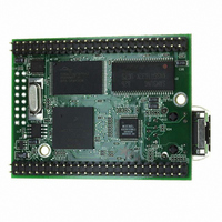
MOD5272-100IR NetBurner Inc, MOD5272-100IR Datasheet - Page 483

MOD5272-100IR
Manufacturer Part Number
MOD5272-100IR
Description
PROCESSOR MODULE FLASH MOD5272
Manufacturer
NetBurner Inc
Type
Controllers & Processorsr
Datasheets
1.MOD5272-100IR.pdf
(2 pages)
2.MOD5272-100IR.pdf
(3 pages)
3.MOD5272-100IR.pdf
(550 pages)
Specifications of MOD5272-100IR
Module/board Type
Processor Module
Ethernet Connection Type
10/100 Ethernet Port RJ-45
Operating Voltage
3.3 V
Product
Modules
Lead Free Status / RoHS Status
Lead free / RoHS Compliant
For Use With/related Products
MOD5272
For Use With
528-1001 - KIT DEVELOP NETWORK FOR MOD5272
Lead Free Status / Rohs Status
Lead free / RoHS Compliant
Other names
528-1008
- Current page: 483 of 550
- Download datasheet (6Mb)
MOTOROLA
Chapter 21
IEEE 1149.1 Test Access Port (JTAG)
This chapter describes the dedicated user-accessible test logic implemented on the
MCF5272. This test logic complies fully with the IEEE 1149.1 Standard Test Access Port
and Boundary Scan Architecture. This chapter describes those items required by the
standard and provides additional information specific to the MCF5272 implementation. For
internal details and sample applications, see the IEEE 1149.1 document.
21.1 Overview
Problems with testing high-density circuit boards led to development of this standard under
the sponsorship of the Test Technology Committee of IEEE and the Joint Test Action Group
(JTAG). The MCF5272 supports circuit board test strategies based on this standard.
The test logic includes a test access port (TAP) consisting a 16-state controller, an
instruction register, and three test registers (a 1-bit bypass register, a 265-bit boundary-scan
register, and a 32-bit ID register). The boundary scan register links the device’s pins into
one shift register. The contents of this register can be found at the ColdFire website at
http://www.motorola.com/semiconductors. Test logic, implemented using static logic
design, is independent of the device system logic. The TAP includes the following
dedicated signals:
These signals, described in detail in Table 21-1, are enabled by negating the Motorola test
mode signal (MTMOD).
• TCK—Test clock input to synchronize the test logic.
• TMS—Test mode select input (with an internal pullup resistor) that is sampled on
• TDI—Test data input (with an internal pull-up resistor) that is sampled on the rising
• TDO—three-state test data output that is actively driven in the shift-IR and shift-DR
the rising edge of TCK to sequence the TAP controller's state machine.
edge of TCK.
controller states. TDO changes on the falling edge of TCK.
Chapter 21. IEEE 1149.1 Test Access Port (JTAG)
21-1
Related parts for MOD5272-100IR
Image
Part Number
Description
Manufacturer
Datasheet
Request
R

Part Number:
Description:
Ethernet Modules & Development Tools MOD5272 Processor Board
Manufacturer:
NetBurner Inc
Datasheet:

Part Number:
Description:
Ethernet Modules & Development Tools MOD5272 Industrial Temperature
Manufacturer:
NetBurner Inc

Part Number:
Description:
Ethernet Modules & Development Tools MOD5272 MODULE
Manufacturer:
NetBurner Inc
Datasheet:

Part Number:
Description:
PROCESSOR MODULE FLASH
Manufacturer:
NetBurner Inc
Datasheet:

Part Number:
Description:
Ethernet Modules & Development Tools 32Bit 62MHz Core Module 50Pin DIP
Manufacturer:
NetBurner Inc
Datasheet:

Part Number:
Description:
BOARD SERIAL-ETHERNET 512K FLASH
Manufacturer:
NetBurner Inc
Datasheet:

Part Number:
Description:
PROCESSOR MODULE 512KB FLASH
Manufacturer:
NetBurner Inc
Datasheet:

Part Number:
Description:
DUAL PORT SERIAL-ETHERNET
Manufacturer:
NetBurner Inc
Datasheet:

Part Number:
Description:
PROCESSOR MODULE 512KB FLASH
Manufacturer:
NetBurner Inc
Datasheet:

Part Number:
Description:
MOD5234 10/100 ETHERNET MODULE
Manufacturer:
NetBurner Inc
Datasheet:

Part Number:
Description:
KIT DEVELOP NETWORK FOR MOD5282
Manufacturer:
NetBurner Inc
Datasheet:

Part Number:
Description:
KIT DEVELOP NETWORK FOR MOD5272
Manufacturer:
NetBurner Inc
Datasheet:

Part Number:
Description:
Ethernet ICs 32bit 147MHz CAN-to- Ethnt Device IndTemp
Manufacturer:
NetBurner Inc
Datasheet:


