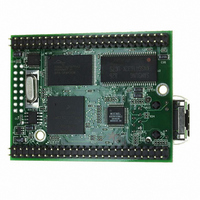
MOD5272-100IR NetBurner Inc, MOD5272-100IR Datasheet - Page 291

MOD5272-100IR
Manufacturer Part Number
MOD5272-100IR
Description
PROCESSOR MODULE FLASH MOD5272
Manufacturer
NetBurner Inc
Type
Controllers & Processorsr
Datasheets
1.MOD5272-100IR.pdf
(2 pages)
2.MOD5272-100IR.pdf
(3 pages)
3.MOD5272-100IR.pdf
(550 pages)
Specifications of MOD5272-100IR
Module/board Type
Processor Module
Ethernet Connection Type
10/100 Ethernet Port RJ-45
Operating Voltage
3.3 V
Product
Modules
Lead Free Status / RoHS Status
Lead free / RoHS Compliant
For Use With/related Products
MOD5272
For Use With
528-1001 - KIT DEVELOP NETWORK FOR MOD5272
Lead Free Status / Rohs Status
Lead free / RoHS Compliant
Other names
528-1008
- Current page: 291 of 550
- Download datasheet (6Mb)
MOTOROLA
12.4.4.1.1 IN Endpoints
The following example demonstrates how to transmit a transfer on an IN endpoint:
12.4.4.1.2 OUT Endpoints
The following example demonstrates how to handle a received transfer on an OUT
endpoint:
12.4.4.2 Isochronous Endpoints
The data flow for isochronous endpoints must be handled differently than the data flow for
non-isochronous endpoints. Data on isochronous endpoints is generally streaming data.
Therefore, there is no concept of transfers and EOT. In addition, isochronous endpoints
differ from other endpoint types in two distinct ways. Isochronous endpoints support packet
sizes up to 1023 bytes and isochronous packets are never resent. In order to support the
large packet sizes, the FIFO size can be less than two times the packet size and the EPDPn
registers are updated in real-time, not just at the end of a packet as with other endpoint
types. If the packet size is larger than the FIFO size, the FIFO level interrupt must be used.
1. Wait until the last transfer is complete (an EOT interrupt has occurred).
2. Write data to the FIFO to fill it.
3. Wait for EOP interrupt or poll EOP bit.
4. Read EPnDP to determine the number of bytes that can be written to the FIFO.
5. Write data to the FIFO to fill it or until all of the data for the transfer has been
6. Repeat steps 5–7 until all of the data for the transfer has been written to the FIFO.
7. Clear EPnCTL[IN_DONE].
8. Wait for the EOT interrupt or poll the EOT bit. The user can now begin processing
1. Wait for the EOP interrupt or poll the EOP bit.
2. Read EPnDP to determine number of bytes in the FIFO.
3. Read the indicated number of bytes of data from the FIFO into a buffer.
4. Repeat steps 1–3 until EOT is set.
5. When EOT is set, the transfer is complete. While EOT is set, the FIFO is locked and
6. Read EPnDP to determine the number of bytes in the FIFO if any for the last transfer.
7. Read the indicated number of bytes of data from the FIFO into a buffer.
8. The user can now process the received transfer.
Normally, only one packet should be written unless the software does not service the
EOP immediately.
written.
the next transfer.
any packets sent for the next transfer cause a NAK response.
The EOT bit can be cleared once this register has been read.
Chapter 12. Universal Serial Bus (USB)
Software Architecture and Application Notes
12-31
Related parts for MOD5272-100IR
Image
Part Number
Description
Manufacturer
Datasheet
Request
R

Part Number:
Description:
Ethernet Modules & Development Tools MOD5272 Processor Board
Manufacturer:
NetBurner Inc
Datasheet:

Part Number:
Description:
Ethernet Modules & Development Tools MOD5272 Industrial Temperature
Manufacturer:
NetBurner Inc

Part Number:
Description:
Ethernet Modules & Development Tools MOD5272 MODULE
Manufacturer:
NetBurner Inc
Datasheet:

Part Number:
Description:
PROCESSOR MODULE FLASH
Manufacturer:
NetBurner Inc
Datasheet:

Part Number:
Description:
Ethernet Modules & Development Tools 32Bit 62MHz Core Module 50Pin DIP
Manufacturer:
NetBurner Inc
Datasheet:

Part Number:
Description:
BOARD SERIAL-ETHERNET 512K FLASH
Manufacturer:
NetBurner Inc
Datasheet:

Part Number:
Description:
PROCESSOR MODULE 512KB FLASH
Manufacturer:
NetBurner Inc
Datasheet:

Part Number:
Description:
DUAL PORT SERIAL-ETHERNET
Manufacturer:
NetBurner Inc
Datasheet:

Part Number:
Description:
PROCESSOR MODULE 512KB FLASH
Manufacturer:
NetBurner Inc
Datasheet:

Part Number:
Description:
MOD5234 10/100 ETHERNET MODULE
Manufacturer:
NetBurner Inc
Datasheet:

Part Number:
Description:
KIT DEVELOP NETWORK FOR MOD5282
Manufacturer:
NetBurner Inc
Datasheet:

Part Number:
Description:
KIT DEVELOP NETWORK FOR MOD5272
Manufacturer:
NetBurner Inc
Datasheet:

Part Number:
Description:
Ethernet ICs 32bit 147MHz CAN-to- Ethnt Device IndTemp
Manufacturer:
NetBurner Inc
Datasheet:


