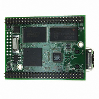
MOD5272-100IR NetBurner Inc, MOD5272-100IR Datasheet - Page 496

MOD5272-100IR
Manufacturer Part Number
MOD5272-100IR
Description
PROCESSOR MODULE FLASH MOD5272
Manufacturer
NetBurner Inc
Type
Controllers & Processorsr
Datasheets
1.MOD5272-100IR.pdf
(2 pages)
2.MOD5272-100IR.pdf
(3 pages)
3.MOD5272-100IR.pdf
(550 pages)
Specifications of MOD5272-100IR
Module/board Type
Processor Module
Ethernet Connection Type
10/100 Ethernet Port RJ-45
Operating Voltage
3.3 V
Product
Modules
Lead Free Status / RoHS Status
Lead free / RoHS Compliant
For Use With/related Products
MOD5272
For Use With
528-1001 - KIT DEVELOP NETWORK FOR MOD5272
Lead Free Status / Rohs Status
Lead free / RoHS Compliant
Other names
528-1008
- Current page: 496 of 550
- Download datasheet (6Mb)
Maximum Ratings
23.1.2 Operating Temperature
Table 23-2 lists operating temperatures.
23.1.3 Resistance
Table 23-3 lists thermal resistance values.
23-2
1
2
3
4
5
6
Junction to ambient, natural convection
Junction to ambient, natural convection
Junction to ambient (@200 ft/min)
Junction to ambient (@200 ft/min)
Junction to board
Junction to case
Junction to top of package
1
Maximum operating junction temperature
Maximum operating ambient temperature
Minimum operating ambient temperature
θ
Motorola recommends the use of θ
device junction temperatures from exceeding the rated specification. System designers should be aware that
device junction temperatures can be significantly influenced by board layout and surrounding devices.
Conformance to the device junction temperature specification can be verified by physical measurement in the
customer’s system using the Ψ
EIA/JESD Standard 51-2.
Per SEMI G38-87 and JEDEC JESD51-2 with the single layer board horizontal.
Per JEDEC JESD51-6 with the board horizontal.
Thermal resistance between the die and the printed circuit board per JEDEC JESD51-8. Board temperature is
measured on the top surface of the board near the package.
Thermal resistance between the die and the case top surface as measured by the cold plate method (MIL
SPEC-883 Method 1012.1).
Thermal characterization parameter indicating the temperature difference between package top and the
junction temperature per JEDEC JESD51-2. When Greek letters are not available, the thermal
characterization parameter is written as Psi-JT.
JA
Use this maximum operating ambient temperature only as a system design guideline. All device operating
parameters are guaranteed only when the junction temperature lies within the specified range.
and Ψ
jt
parameters are simulated in accordance with EIA/JESD Standard 51-2 for natural convection.
Characteristic
Characteristic
Table 23-2. Operating Temperature
jt
parameter, the device power dissipation, and the method described in
Table 23-3. Thermal Resistance
JA
and power dissipation specifications in the system design to prevent
MCF5272 User’s Manual
Single layer board (1s)
Four layer board (2s2p)
Single layer board (1s)
Four layer board (2s2p)
Natural convection
Symbol
T
T
Amax
Amin
T
J
Standard
Symbol
100
70
θ
θ
θ
θ
0
θ
θ
Ψ
JMA
JMA
JMA
1
JA
JB
JC
jt
Value
Extended
115
85
-40
Value
51
26
41
23
2
15
10
1
1,6
1,2
1,3
1,3
1,3
4
5
MOTOROLA
Unit
°C
°C
°C
°C/W
°C/W
°C/W
°C/W
°C/W
°C/W
°C/W
Unit
Related parts for MOD5272-100IR
Image
Part Number
Description
Manufacturer
Datasheet
Request
R

Part Number:
Description:
Ethernet Modules & Development Tools MOD5272 Processor Board
Manufacturer:
NetBurner Inc
Datasheet:

Part Number:
Description:
Ethernet Modules & Development Tools MOD5272 Industrial Temperature
Manufacturer:
NetBurner Inc

Part Number:
Description:
Ethernet Modules & Development Tools MOD5272 MODULE
Manufacturer:
NetBurner Inc
Datasheet:

Part Number:
Description:
PROCESSOR MODULE FLASH
Manufacturer:
NetBurner Inc
Datasheet:

Part Number:
Description:
Ethernet Modules & Development Tools 32Bit 62MHz Core Module 50Pin DIP
Manufacturer:
NetBurner Inc
Datasheet:

Part Number:
Description:
BOARD SERIAL-ETHERNET 512K FLASH
Manufacturer:
NetBurner Inc
Datasheet:

Part Number:
Description:
PROCESSOR MODULE 512KB FLASH
Manufacturer:
NetBurner Inc
Datasheet:

Part Number:
Description:
DUAL PORT SERIAL-ETHERNET
Manufacturer:
NetBurner Inc
Datasheet:

Part Number:
Description:
PROCESSOR MODULE 512KB FLASH
Manufacturer:
NetBurner Inc
Datasheet:

Part Number:
Description:
MOD5234 10/100 ETHERNET MODULE
Manufacturer:
NetBurner Inc
Datasheet:

Part Number:
Description:
KIT DEVELOP NETWORK FOR MOD5282
Manufacturer:
NetBurner Inc
Datasheet:

Part Number:
Description:
KIT DEVELOP NETWORK FOR MOD5272
Manufacturer:
NetBurner Inc
Datasheet:

Part Number:
Description:
Ethernet ICs 32bit 147MHz CAN-to- Ethnt Device IndTemp
Manufacturer:
NetBurner Inc
Datasheet:


