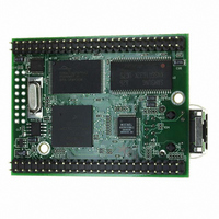
MOD5272-100IR NetBurner Inc, MOD5272-100IR Datasheet - Page 289

MOD5272-100IR
Manufacturer Part Number
MOD5272-100IR
Description
PROCESSOR MODULE FLASH MOD5272
Manufacturer
NetBurner Inc
Type
Controllers & Processorsr
Datasheets
1.MOD5272-100IR.pdf
(2 pages)
2.MOD5272-100IR.pdf
(3 pages)
3.MOD5272-100IR.pdf
(550 pages)
Specifications of MOD5272-100IR
Module/board Type
Processor Module
Ethernet Connection Type
10/100 Ethernet Port RJ-45
Operating Voltage
3.3 V
Product
Modules
Lead Free Status / RoHS Status
Lead free / RoHS Compliant
For Use With/related Products
MOD5272
For Use With
528-1001 - KIT DEVELOP NETWORK FOR MOD5272
Lead Free Status / Rohs Status
Lead free / RoHS Compliant
Other names
528-1008
- Current page: 289 of 550
- Download datasheet (6Mb)
MOTOROLA
12.4.2 USB Configuration and Interface Changes
Although the USB module handles the SET_CONFIGURATION and SET_INTERFACE
requests, the user is still required to perform some initialization when the configuration or
alternate settings change. A configuration or alternate setting change is signaled by the
DEV_CFG interrupt. The following steps are required to service the DEV_CFG interrupt.
12.4.3 FIFO Configuration
The USB module allows a very flexible FIFO configuration. The FIFO configuration is very
application dependent. The FIFO configuration depends on the current configuration
number, alternate setting for each interface, and each endpoint’s type and packet size. The
USB module contains two separate 512-byte FIFO spaces: one for IN and one for OUT
endpoints. The following guidelines must be adhered to when configuring the FIFO’s:
1. Clear EP0CTL[CFG_RAM_VAL,USB_EN].
2. Load the configuration RAM with the descriptors from external ROM. The starting
3. Select the internal or external USB transceiver in EPC0TL.
4. Write IEP0CFG and OEP0CFG to initialize the EP0 IN and OUT FIFOs.
5. Initialize the EP0 interrupt vectors.
6. Clear all interrupt bits in EP0ISR.
7. Enable the desired EP0 interrupt sources in EP0IMR.
8. Set EP0CTL[USB_EN, CFG_RAM_VALID].
1. Read EPSR0 and ASR to determine the current configuration and alternate settings.
2. Read the endpoint descriptors for the current configuration and alternate settings to
3. Write EPnCFG for all active endpoints to initialize the FIFOs.
4. Initialize the interrupt vectors for the active endpoints.
5. Clear all interrupt bits in the EPnISR registers for all active endpoints.
6. Enable the desired interrupt sources in the EPnIMR registers.
7. Clear the DEV_CFG interrupt bit to allow the USB module to access the FIFOs.
• The MAX_PACKET field in the EPnCFG registers must match the
• EPnCFG[FIFO_SIZE] must be a power of 2 and must be at least two packets for
configuration RAM address is MBAR + 0x1400.
determine the endpoint type and maximum packet size for all of the active
endpoints.
wMaxPacketSize field in the corresponding endpoint descriptor. An incorrect setting
causes USB errors and unexpected interrupts.
non-isochronous endpoints.
Chapter 12. Universal Serial Bus (USB)
Software Architecture and Application Notes
12-29
Related parts for MOD5272-100IR
Image
Part Number
Description
Manufacturer
Datasheet
Request
R

Part Number:
Description:
Ethernet Modules & Development Tools MOD5272 Processor Board
Manufacturer:
NetBurner Inc
Datasheet:

Part Number:
Description:
Ethernet Modules & Development Tools MOD5272 Industrial Temperature
Manufacturer:
NetBurner Inc

Part Number:
Description:
Ethernet Modules & Development Tools MOD5272 MODULE
Manufacturer:
NetBurner Inc
Datasheet:

Part Number:
Description:
PROCESSOR MODULE FLASH
Manufacturer:
NetBurner Inc
Datasheet:

Part Number:
Description:
Ethernet Modules & Development Tools 32Bit 62MHz Core Module 50Pin DIP
Manufacturer:
NetBurner Inc
Datasheet:

Part Number:
Description:
BOARD SERIAL-ETHERNET 512K FLASH
Manufacturer:
NetBurner Inc
Datasheet:

Part Number:
Description:
PROCESSOR MODULE 512KB FLASH
Manufacturer:
NetBurner Inc
Datasheet:

Part Number:
Description:
DUAL PORT SERIAL-ETHERNET
Manufacturer:
NetBurner Inc
Datasheet:

Part Number:
Description:
PROCESSOR MODULE 512KB FLASH
Manufacturer:
NetBurner Inc
Datasheet:

Part Number:
Description:
MOD5234 10/100 ETHERNET MODULE
Manufacturer:
NetBurner Inc
Datasheet:

Part Number:
Description:
KIT DEVELOP NETWORK FOR MOD5282
Manufacturer:
NetBurner Inc
Datasheet:

Part Number:
Description:
KIT DEVELOP NETWORK FOR MOD5272
Manufacturer:
NetBurner Inc
Datasheet:

Part Number:
Description:
Ethernet ICs 32bit 147MHz CAN-to- Ethnt Device IndTemp
Manufacturer:
NetBurner Inc
Datasheet:


