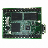
MOD5272-100IR NetBurner Inc, MOD5272-100IR Datasheet - Page 302

MOD5272-100IR
Manufacturer Part Number
MOD5272-100IR
Description
PROCESSOR MODULE FLASH MOD5272
Manufacturer
NetBurner Inc
Type
Controllers & Processorsr
Datasheets
1.MOD5272-100IR.pdf
(2 pages)
2.MOD5272-100IR.pdf
(3 pages)
3.MOD5272-100IR.pdf
(550 pages)
Specifications of MOD5272-100IR
Module/board Type
Processor Module
Ethernet Connection Type
10/100 Ethernet Port RJ-45
Operating Voltage
3.3 V
Product
Modules
Lead Free Status / RoHS Status
Lead free / RoHS Compliant
For Use With/related Products
MOD5272
For Use With
528-1001 - KIT DEVELOP NETWORK FOR MOD5272
Lead Free Status / Rohs Status
Lead free / RoHS Compliant
Other names
528-1008
- Current page: 302 of 550
- Download datasheet (6Mb)
GCI/IDL Block
frame in the most significant byte (MSB) position, and the fourth frame taking the least
significant byte (LSB) position. See Section 13.5.1, “B1 Data Receive Registers
(P0B1RR–P3B1RR),”
(P0B2TR–P3B2TR),” for more information about some of these registers.
13.2.3.2 B-Channel HDLC Encoded Data
When the incoming B channels contain HDLC encoded data they are presented on the
physical line least significant bit (lsb) first. The Soft HDLC expects the first bit received to
be aligned in the lsb position of a byte, with the last bit received aligned in the msb position.
Because the presentation of HDLC encoded data on the physical interface is lsb (least
significant bit) first for B1 and B2 the lsb is right-aligned in the transmit and receive shift
register, that is, the first bit of the B-channel received is aligned in the lsb position through
to the last received bit of a byte that is aligned in the msb position.
The ordering of the bytes over four frames within the longword register is as for unencoded
data; that is, the first frame is aligned in the MSB through to the fourth frame, which is
aligned in the LSB position. See Figure 13-6.
13-6
Unencoded
.
32-bit B1/B2 Receive/Transmit Registers, PnB1RR, PnB2RR, PnB1TR, PnB2TR
HDLC
Encoded
Din/Dout
Din/Dout
B
7
DCL
FSR
B
6
B
5
Frame 0
B
Figure 13-6. B-Channel Unencoded and HDLC Encoded Data
4
B
B
B
3
7
0
B
B
B
2
6
1
B
B
B
1
5
2
B
B
B
4
3
0
B 1
B
B
B
3
4
or
7
B
B
B
2
5
6
B
B
B
1
6
5
Section 13.5.5,
Frame 1
B
B
B
0
7
Frame 0
4
MCF5272 User’s Manual
B
B
B
7
0
3
B
B
1
B
6
2
B
B
5
2
B
B
B
1
4
3
B 2
B
B
B
0
3
4
B
B
B
7
2
5
B
B
B
6
6
1
“B2
B
B
B
5
7
0
Frame 2
D
D
B
4
0
0
D
D
D
B
1
1
3
Data
B
2
B
1
B
0
B
Transmit
7
B
6
B
Frame 3
5
B
B
7
0
B
B
B
4
6
1
B
Frame 1
B
B
3
MOTOROLA
5
2
B
Registers
B
B
2
4
3
B
B
B
1
3
4
B
B
B
0
2
5
Related parts for MOD5272-100IR
Image
Part Number
Description
Manufacturer
Datasheet
Request
R

Part Number:
Description:
Ethernet Modules & Development Tools MOD5272 Processor Board
Manufacturer:
NetBurner Inc
Datasheet:

Part Number:
Description:
Ethernet Modules & Development Tools MOD5272 Industrial Temperature
Manufacturer:
NetBurner Inc

Part Number:
Description:
Ethernet Modules & Development Tools MOD5272 MODULE
Manufacturer:
NetBurner Inc
Datasheet:

Part Number:
Description:
PROCESSOR MODULE FLASH
Manufacturer:
NetBurner Inc
Datasheet:

Part Number:
Description:
Ethernet Modules & Development Tools 32Bit 62MHz Core Module 50Pin DIP
Manufacturer:
NetBurner Inc
Datasheet:

Part Number:
Description:
BOARD SERIAL-ETHERNET 512K FLASH
Manufacturer:
NetBurner Inc
Datasheet:

Part Number:
Description:
PROCESSOR MODULE 512KB FLASH
Manufacturer:
NetBurner Inc
Datasheet:

Part Number:
Description:
DUAL PORT SERIAL-ETHERNET
Manufacturer:
NetBurner Inc
Datasheet:

Part Number:
Description:
PROCESSOR MODULE 512KB FLASH
Manufacturer:
NetBurner Inc
Datasheet:

Part Number:
Description:
MOD5234 10/100 ETHERNET MODULE
Manufacturer:
NetBurner Inc
Datasheet:

Part Number:
Description:
KIT DEVELOP NETWORK FOR MOD5282
Manufacturer:
NetBurner Inc
Datasheet:

Part Number:
Description:
KIT DEVELOP NETWORK FOR MOD5272
Manufacturer:
NetBurner Inc
Datasheet:

Part Number:
Description:
Ethernet ICs 32bit 147MHz CAN-to- Ethnt Device IndTemp
Manufacturer:
NetBurner Inc
Datasheet:


