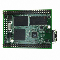
MOD5272-100IR NetBurner Inc, MOD5272-100IR Datasheet - Page 126

MOD5272-100IR
Manufacturer Part Number
MOD5272-100IR
Description
PROCESSOR MODULE FLASH MOD5272
Manufacturer
NetBurner Inc
Type
Controllers & Processorsr
Datasheets
1.MOD5272-100IR.pdf
(2 pages)
2.MOD5272-100IR.pdf
(3 pages)
3.MOD5272-100IR.pdf
(550 pages)
Specifications of MOD5272-100IR
Module/board Type
Processor Module
Ethernet Connection Type
10/100 Ethernet Port RJ-45
Operating Voltage
3.3 V
Product
Modules
Lead Free Status / RoHS Status
Lead free / RoHS Compliant
For Use With/related Products
MOD5272
For Use With
528-1001 - KIT DEVELOP NETWORK FOR MOD5272
Lead Free Status / Rohs Status
Lead free / RoHS Compliant
Other names
528-1008
- Current page: 126 of 550
- Download datasheet (6Mb)
Real-Time Trace Support
5.3.1 Begin Execution of Taken Branch (PST = 0x5)
PST is 0x5 when a taken branch is executed. For some opcodes, a branch target address may
be displayed on DDATA depending on the CSR settings. CSR also controls the number of
address bytes displayed, which is indicated by the PST marker value immediately
preceding the DDATA nibble that begins the data output.
Bytes are displayed in least-to-most-significant order. The processor captures only those
target addresses associated with taken branches which use a variant addressing mode, that
is, RTE and RTS instructions, JMP and JSR instructions using address register indirect or
indexed addressing modes, and all exception vectors.
The simplest example of a branch instruction using a variant address is the compiled code
for a C language case statement. Typically, the evaluation of this statement uses the variable
of an expression as an index into a table of offsets, where each offset points to a unique case
within the structure. For such change-of-flow operations, the MCF5272 uses the debug pins
to output the following sequence of information on successive processor clock cycles:
Another example of a variant branch instruction would be a JMP (A0) instruction. Figure
shows when the PST and DDATA outputs that indicate when a JMP (A0) executed,
assuming the CSR was programmed to display the lower 2 bytes of an address.
Hex
0xC
0xD
0xE
0xF
5-4
PST[3:0]
1. Use PST (0x5) to identify that a taken branch was executed.
2. Using the PST pins, optionally signal the target address to be displayed sequentially
3. The new target address is optionally available on subsequent cycles using the
Binary
1100
1101
1110
1111
on the DDATA pins. Encodings 0x9–0xB identify the number of bytes displayed.
DDATA port. The number of bytes of the target address displayed on this port is
configurable (2, 3, or 4 bytes).
Exception processing. Exceptions that enter emulation mode (debug interrupt or optionally trace)
generate a different encoding, as described below. Because the 0xC encoding defines a multiple-cycle
mode, PST outputs are driven with 0xC until exception processing completes.
Entry into emulator mode. Displayed during emulation mode (debug interrupt or optionally trace).
Because this encoding defines a multiple-cycle mode, PST outputs are driven with 0xD until exception
processing completes.
Processor is stopped. Appears in multiple-cycle format when the MCF5272 executes a STOP
instruction. The ColdFire processor remains stopped until an interrupt occurs, thus PST outputs
display 0xE until the stopped mode is exited
Processor is halted. Because this encoding defines a multiple-cycle mode, the PST outputs display
0xF until the processor is restarted or reset. (see Section 5.5.1, “CPU Halt”)
Table 5-2. Processor Status Encoding (Continued)
MCF5272 User’s Manual
.
Definition
MOTOROLA
Related parts for MOD5272-100IR
Image
Part Number
Description
Manufacturer
Datasheet
Request
R

Part Number:
Description:
Ethernet Modules & Development Tools MOD5272 Processor Board
Manufacturer:
NetBurner Inc
Datasheet:

Part Number:
Description:
Ethernet Modules & Development Tools MOD5272 Industrial Temperature
Manufacturer:
NetBurner Inc

Part Number:
Description:
Ethernet Modules & Development Tools MOD5272 MODULE
Manufacturer:
NetBurner Inc
Datasheet:

Part Number:
Description:
PROCESSOR MODULE FLASH
Manufacturer:
NetBurner Inc
Datasheet:

Part Number:
Description:
Ethernet Modules & Development Tools 32Bit 62MHz Core Module 50Pin DIP
Manufacturer:
NetBurner Inc
Datasheet:

Part Number:
Description:
BOARD SERIAL-ETHERNET 512K FLASH
Manufacturer:
NetBurner Inc
Datasheet:

Part Number:
Description:
PROCESSOR MODULE 512KB FLASH
Manufacturer:
NetBurner Inc
Datasheet:

Part Number:
Description:
DUAL PORT SERIAL-ETHERNET
Manufacturer:
NetBurner Inc
Datasheet:

Part Number:
Description:
PROCESSOR MODULE 512KB FLASH
Manufacturer:
NetBurner Inc
Datasheet:

Part Number:
Description:
MOD5234 10/100 ETHERNET MODULE
Manufacturer:
NetBurner Inc
Datasheet:

Part Number:
Description:
KIT DEVELOP NETWORK FOR MOD5282
Manufacturer:
NetBurner Inc
Datasheet:

Part Number:
Description:
KIT DEVELOP NETWORK FOR MOD5272
Manufacturer:
NetBurner Inc
Datasheet:

Part Number:
Description:
Ethernet ICs 32bit 147MHz CAN-to- Ethnt Device IndTemp
Manufacturer:
NetBurner Inc
Datasheet:


