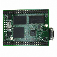
MOD5272-100IR NetBurner Inc, MOD5272-100IR Datasheet - Page 286

MOD5272-100IR
Manufacturer Part Number
MOD5272-100IR
Description
PROCESSOR MODULE FLASH MOD5272
Manufacturer
NetBurner Inc
Type
Controllers & Processorsr
Datasheets
1.MOD5272-100IR.pdf
(2 pages)
2.MOD5272-100IR.pdf
(3 pages)
3.MOD5272-100IR.pdf
(550 pages)
Specifications of MOD5272-100IR
Module/board Type
Processor Module
Ethernet Connection Type
10/100 Ethernet Port RJ-45
Operating Voltage
3.3 V
Product
Modules
Lead Free Status / RoHS Status
Lead free / RoHS Compliant
For Use With/related Products
MOD5272
For Use With
528-1001 - KIT DEVELOP NETWORK FOR MOD5272
Lead Free Status / Rohs Status
Lead free / RoHS Compliant
Other names
528-1008
- Current page: 286 of 550
- Download datasheet (6Mb)
Register Description and Programming Model
Table 12-18 describes EPDPn fields.
12.3.3 Configuration RAM
The USB module supports up to 1 KByte of USB descriptors. The configuration RAM
begins
EPCTL0[CFG_RAM_VAL] must be cleared to access the configuration RAM, otherwise
an access error results.
12.3.3.1 Configuration RAM Content
The USB host must configure a device before that device’s function can be used. The host
configures the device by first reading the descriptors for the device. The descriptors must
follow the format described in Chapter 9 of the USB specification and any relevant class
specification.
A device may support multiple configurations. Within any one configuration, the device
may support multiple interfaces. An interface consists of a set of endpoints that presents to
the host a single feature or function of the device. An interface within a configuration may
have alternate settings that redefine the characteristics of the associated endpoints. All
devices must provide a device descriptor and at least one configuration, interface and
endpoint descriptor. Each configuration must have at least one interface and one endpoint
descriptor. Only one configuration is effective at any time, but several interfaces and their
related endpoints may be operational at the same time. Only one setting for a particular
interface is effective at any time.
12-26
15–9
Bits
8–0
at
Name
DATA_PRES Endpoint n data present. This field reflects the number of bytes in the endpoint’s FIFO.
The USB descriptors use little endian format for word and
longword fields. The MCF5272 uses big endian format for
words and longwords. The user must make sure that any word
or longword fields are stored in the correct byte order.
address
—
Description
Reserved, should be cleared.
This field is updated when the user writes to or reads from the FIFO and when the control
logic accesses the FIFO. For non-isochronous endpoints, the FIFO level is only updated
when a complete packet is received or transmitted without any errors. This occurs
synchronously with an EOP interrupt. For isochronous endpoints, the FIFO level is
updated by the control logic in real-time rather than only after the transfer of a complete
packet.
Note: for non-isochronous OUT endpoints, this field is frozen while an EOT interrupt is
pending in order to allow the user to determine the number of bytes to read for the last
transfer. For endpoint 0, EPDP0 monitors the OUT FIFO only.
Table 12-18. EP
MBAR
+
MCF5272 User’s Manual
0x1400
n
NOTE:
DPR Field Descriptions
and
is
longword
accessible
MOTOROLA
only.
Related parts for MOD5272-100IR
Image
Part Number
Description
Manufacturer
Datasheet
Request
R

Part Number:
Description:
Ethernet Modules & Development Tools MOD5272 Processor Board
Manufacturer:
NetBurner Inc
Datasheet:

Part Number:
Description:
Ethernet Modules & Development Tools MOD5272 Industrial Temperature
Manufacturer:
NetBurner Inc

Part Number:
Description:
Ethernet Modules & Development Tools MOD5272 MODULE
Manufacturer:
NetBurner Inc
Datasheet:

Part Number:
Description:
PROCESSOR MODULE FLASH
Manufacturer:
NetBurner Inc
Datasheet:

Part Number:
Description:
Ethernet Modules & Development Tools 32Bit 62MHz Core Module 50Pin DIP
Manufacturer:
NetBurner Inc
Datasheet:

Part Number:
Description:
BOARD SERIAL-ETHERNET 512K FLASH
Manufacturer:
NetBurner Inc
Datasheet:

Part Number:
Description:
PROCESSOR MODULE 512KB FLASH
Manufacturer:
NetBurner Inc
Datasheet:

Part Number:
Description:
DUAL PORT SERIAL-ETHERNET
Manufacturer:
NetBurner Inc
Datasheet:

Part Number:
Description:
PROCESSOR MODULE 512KB FLASH
Manufacturer:
NetBurner Inc
Datasheet:

Part Number:
Description:
MOD5234 10/100 ETHERNET MODULE
Manufacturer:
NetBurner Inc
Datasheet:

Part Number:
Description:
KIT DEVELOP NETWORK FOR MOD5282
Manufacturer:
NetBurner Inc
Datasheet:

Part Number:
Description:
KIT DEVELOP NETWORK FOR MOD5272
Manufacturer:
NetBurner Inc
Datasheet:

Part Number:
Description:
Ethernet ICs 32bit 147MHz CAN-to- Ethnt Device IndTemp
Manufacturer:
NetBurner Inc
Datasheet:


