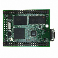
MOD5272-100IR NetBurner Inc, MOD5272-100IR Datasheet - Page 13

MOD5272-100IR
Manufacturer Part Number
MOD5272-100IR
Description
PROCESSOR MODULE FLASH MOD5272
Manufacturer
NetBurner Inc
Type
Controllers & Processorsr
Datasheets
1.MOD5272-100IR.pdf
(2 pages)
2.MOD5272-100IR.pdf
(3 pages)
3.MOD5272-100IR.pdf
(550 pages)
Specifications of MOD5272-100IR
Module/board Type
Processor Module
Ethernet Connection Type
10/100 Ethernet Port RJ-45
Operating Voltage
3.3 V
Product
Modules
Lead Free Status / RoHS Status
Lead free / RoHS Compliant
For Use With/related Products
MOD5272
For Use With
528-1001 - KIT DEVELOP NETWORK FOR MOD5272
Lead Free Status / Rohs Status
Lead free / RoHS Compliant
Other names
528-1008
- Current page: 13 of 550
- Download datasheet (6Mb)
MOTOROLA
12.4.4.2
12.4.4.2.1
12.4.4.2.2
12.4.5
12.4.6
12.4.7
12.5
12.5.1
12.5.2
12.5.3
13.1
13.2
13.2.1
13.2.2
13.2.3
13.2.3.1
13.2.3.2
13.2.3.3
13.2.3.4
13.2.3.5
13.2.4
13.2.4.1
13.2.4.2
13.2.4.3
13.2.5
13.2.5.1
13.2.5.2
13.2.5.3
13.3
13.3.1
13.3.2
13.3.3
13.4
13.5
13.5.1
13.5.2
13.5.3
13.5.4
Paragraph
Number
Line Interface .................................................................................................. 12-34
Introduction....................................................................................................... 13-1
GCI/IDL Block ................................................................................................. 13-3
PLIC Timing Generator .................................................................................. 13-11
PLIC Register Memory Map .......................................................................... 13-14
PLIC Registers ................................................................................................ 13-15
Class- and Vendor-Specific Request Operation ......................................... 12-32
remote wakeup and resume Operation........................................................ 12-33
Endpoint Halt Feature................................................................................. 12-33
Attachment Detection ................................................................................. 12-34
PCB Layout Recommendations.................................................................. 12-34
Recommended USB Protection Circuit ...................................................... 12-35
GCI/IDL B- and D-Channel Receive Data Registers ................................... 13-3
GCI/IDL B- and D-Channel Transmit Data Registers.................................. 13-4
GCI/IDL B- and D-Channel Bit Alignment ................................................. 13-5
GCI/IDL Looping Modes ............................................................................. 13-8
GCI/IDL Interrupts ..................................................................................... 13-10
Clock Synthesis........................................................................................... 13-11
Super Frame Sync Generation .................................................................... 13-12
Frame Sync Synthesis................................................................................. 13-13
B1 Data Receive Registers (P0B1RR–P3B1RR) ....................................... 13-15
B2 Data Receive Registers (P0B2RR–P3B2RR) ....................................... 13-16
D Data Receive Registers (P0DRR–P3DRR)............................................. 13-16
B1 Data Transmit Registers (P0B1TR–P3B1TR) ...................................... 13-17
Isochronous Endpoints............................................................................ 12-31
B-Channel Unencoded Data ..................................................................... 13-5
B-Channel HDLC Encoded Data.............................................................. 13-6
D-Channel HDLC Encoded Data ............................................................. 13-7
D-Channel Unencoded Data ..................................................................... 13-7
Automatic Echo Mode .............................................................................. 13-9
Local Loopback Mode .............................................................................. 13-9
Remote Loopback Mode........................................................................... 13-9
GCI/IDL Periodic Frame Interrupt ......................................................... 13-10
Interrupt Control ..................................................................................... 13-11
GCI/IDL D-Channel Contention ............................................................. 13-8
GCI Aperiodic Status Interrupt.............................................................. 13-10
Physical Layer Interface Controller (PLIC)
IN Endpoints....................................................................................... 12-32
OUT Endpoints................................................................................... 12-32
CONTENTS
Chapter 13
Contents
Title
Number
Page
xiii
Related parts for MOD5272-100IR
Image
Part Number
Description
Manufacturer
Datasheet
Request
R

Part Number:
Description:
Ethernet Modules & Development Tools MOD5272 Processor Board
Manufacturer:
NetBurner Inc
Datasheet:

Part Number:
Description:
Ethernet Modules & Development Tools MOD5272 Industrial Temperature
Manufacturer:
NetBurner Inc

Part Number:
Description:
Ethernet Modules & Development Tools MOD5272 MODULE
Manufacturer:
NetBurner Inc
Datasheet:

Part Number:
Description:
PROCESSOR MODULE FLASH
Manufacturer:
NetBurner Inc
Datasheet:

Part Number:
Description:
Ethernet Modules & Development Tools 32Bit 62MHz Core Module 50Pin DIP
Manufacturer:
NetBurner Inc
Datasheet:

Part Number:
Description:
BOARD SERIAL-ETHERNET 512K FLASH
Manufacturer:
NetBurner Inc
Datasheet:

Part Number:
Description:
PROCESSOR MODULE 512KB FLASH
Manufacturer:
NetBurner Inc
Datasheet:

Part Number:
Description:
DUAL PORT SERIAL-ETHERNET
Manufacturer:
NetBurner Inc
Datasheet:

Part Number:
Description:
PROCESSOR MODULE 512KB FLASH
Manufacturer:
NetBurner Inc
Datasheet:

Part Number:
Description:
MOD5234 10/100 ETHERNET MODULE
Manufacturer:
NetBurner Inc
Datasheet:

Part Number:
Description:
KIT DEVELOP NETWORK FOR MOD5282
Manufacturer:
NetBurner Inc
Datasheet:

Part Number:
Description:
KIT DEVELOP NETWORK FOR MOD5272
Manufacturer:
NetBurner Inc
Datasheet:

Part Number:
Description:
Ethernet ICs 32bit 147MHz CAN-to- Ethnt Device IndTemp
Manufacturer:
NetBurner Inc
Datasheet:


