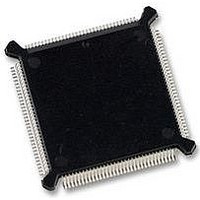
MC68331CEH25 Freescale Semiconductor, MC68331CEH25 Datasheet - Page 89

MC68331CEH25
Manufacturer Part Number
MC68331CEH25
Description
IC MCU 32BIT 25MHZ 132-PQFP
Manufacturer
Freescale Semiconductor
Series
M683xxr
Specifications of MC68331CEH25
Core Processor
CPU32
Core Size
32-Bit
Speed
25MHz
Connectivity
EBI/EMI, SCI, SPI, UART/USART
Peripherals
POR, PWM, WDT
Number Of I /o
18
Program Memory Type
ROMless
Voltage - Supply (vcc/vdd)
4.5 V ~ 5.5 V
Oscillator Type
Internal
Operating Temperature
-40°C ~ 85°C
Package / Case
132-QFP
Controller Family/series
68K
No. Of I/o's
18
Cpu Speed
25MHz
No. Of Timers
1
Embedded Interface Type
QSPI, SCI, UART
No. Of Pwm Channels
2
Digital Ic Case Style
PQFP
Rohs Compliant
Yes
Processor Series
M683xx
Core
CPU32
Data Bus Width
32 bit
Data Ram Size
80 B
Interface Type
QSPI, SCI, UART
Maximum Clock Frequency
25 MHz
Number Of Programmable I/os
18
Number Of Timers
1
Maximum Operating Temperature
+ 85 C
Mounting Style
SMD/SMT
Minimum Operating Temperature
- 40 C
Eeprom Size
-
Ram Size
-
Program Memory Size
-
Data Converters
-
Lead Free Status / Rohs Status
Details
Available stocks
Company
Part Number
Manufacturer
Quantity
Price
Company:
Part Number:
MC68331CEH25
Manufacturer:
PANASONIC
Quantity:
2 000
Company:
Part Number:
MC68331CEH25
Manufacturer:
Freescale Semiconductor
Quantity:
135
Company:
Part Number:
MC68331CEH25
Manufacturer:
Freescale Semiconductor
Quantity:
10 000
4.7.4 Interrupt Processing Summary
MC68331
USER’S MANUAL
begins, a valid interrupt service request has been detected and is pending.
Because the EBI manages external interrupt requests, the SIM IARB value is used for
arbitration between internal and external interrupt requests. The reset value of IARB
for the SIM is %1111, and the reset IARB value for all other modules is %0000.
Although arbitration is intended to deal with simultaneous requests of the same prior-
ity, it always takes place, even when a single source is requesting service. This is im-
portant for two reasons: the EBI does not transfer the interrupt acknowledge read cycle
to the external bus unless the SIM wins contention, and failure to contend causes the
interrupt acknowledge bus cycle to be terminated early, by a bus error.
When arbitration is complete, the module with the highest arbitration priority must ter-
minate the bus cycle. Internal modules place an interrupt vector number on the data
bus and generate appropriate internal cycle termination signals. In the case of an ex-
ternal interrupt request, after the interrupt acknowledge cycle is transferred to the ex-
ternal bus, the appropriate external device must decode the mask value and respond
with a vector number, then generate data and size acknowledge (DSACK) termination
signals, or it must assert the autovector (AVEC) request signal. If the device does not
respond in time, the EBI bus monitor asserts the bus error signal BERR, and a spuri-
ous interrupt exception is taken.
Chip-select logic can also be used to generate internal AVEC or DSACK signals in re-
sponse to interrupt requests from external devices (refer to 4.8.3 Using Chip-Select
Signals for Interrupt Acknowledge). Chip-select address match logic functions only
after the EBI transfers an interrupt acknowledge cycle to the external bus following
IARB contention. If a module makes an interrupt request of a certain priority, and the
appropriate chip-select registers are programmed to generate AVEC or DSACK sig-
nals in response to an interrupt acknowledge cycle for that priority level, chip-select
logic does not respond to the interrupt acknowledge cycle, and the internal module
supplies a vector number and generates internal cycle termination signals.
For periodic timer interrupts, the PIRQ field in the periodic interrupt control register (PI-
CR) determines PIT priority level. A PIRQ value of %000 means that PIT interrupts are
inactive. By hardware convention, when the CPU32 receives simultaneous interrupt
requests of the same level from more than one SIM source (including external devic-
es), the periodic interrupt timer is given the highest priority, followed by the IRQ pins.
A summary of the entire interrupt processing sequence follows. When the sequence
A. The CPU finishes higher priority exception processing or reaches an instruction
B. The processor state is stacked. The S bit in the status register is set, establish-
C. The interrupt acknowledge cycle begins:
boundary.
ing supervisor access level, and bits T1 and T0 are cleared, disabling tracing.
1. FC[2:0] are driven to %111 (CPU space) encoding.
CPU32 interprets multiple vector numbers at the same time, with un-
predictable consequences.
Freescale Semiconductor, Inc.
For More Information On This Product,
SYSTEM INTEGRATION MODULE
Go to: www.freescale.com
4-47
4


