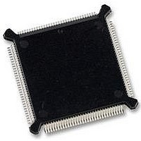
MC68331CEH25 Freescale Semiconductor, MC68331CEH25 Datasheet - Page 12

MC68331CEH25
Manufacturer Part Number
MC68331CEH25
Description
IC MCU 32BIT 25MHZ 132-PQFP
Manufacturer
Freescale Semiconductor
Series
M683xxr
Specifications of MC68331CEH25
Core Processor
CPU32
Core Size
32-Bit
Speed
25MHz
Connectivity
EBI/EMI, SCI, SPI, UART/USART
Peripherals
POR, PWM, WDT
Number Of I /o
18
Program Memory Type
ROMless
Voltage - Supply (vcc/vdd)
4.5 V ~ 5.5 V
Oscillator Type
Internal
Operating Temperature
-40°C ~ 85°C
Package / Case
132-QFP
Controller Family/series
68K
No. Of I/o's
18
Cpu Speed
25MHz
No. Of Timers
1
Embedded Interface Type
QSPI, SCI, UART
No. Of Pwm Channels
2
Digital Ic Case Style
PQFP
Rohs Compliant
Yes
Processor Series
M683xx
Core
CPU32
Data Bus Width
32 bit
Data Ram Size
80 B
Interface Type
QSPI, SCI, UART
Maximum Clock Frequency
25 MHz
Number Of Programmable I/os
18
Number Of Timers
1
Maximum Operating Temperature
+ 85 C
Mounting Style
SMD/SMT
Minimum Operating Temperature
- 40 C
Eeprom Size
-
Ram Size
-
Program Memory Size
-
Data Converters
-
Lead Free Status / Rohs Status
Details
Available stocks
Company
Part Number
Manufacturer
Quantity
Price
Company:
Part Number:
MC68331CEH25
Manufacturer:
PANASONIC
Quantity:
2 000
Company:
Part Number:
MC68331CEH25
Manufacturer:
Freescale Semiconductor
Quantity:
135
Company:
Part Number:
MC68331CEH25
Manufacturer:
Freescale Semiconductor
Quantity:
10 000
Figure
6-3
6-4
6-5
6-5
6-5
6-6
6-6
6-7
6-8
7-1
7-2
7-3
7-4
7-5
7-6
A-1
A-2
A-3
A-4
A-5
A-6
A-7
A-8
A-9
A-10
A-11
A-12
A-13
A-14
A-15
A-16
A-17
A-18
A-19
B-1
B-2
D-1
D-2
QSPI RAM....................................................................................................... 6-7
Flowchart of QSPI Initialization Operation..................................................... 6-11
Flowchart of QSPI Master Operation (Part 1) ............................................... 6-12
Flowchart of QSPI Master Operation (Part 2) ............................................... 6-13
Flowchart of QSPI Master Operation (Part 3) ............................................... 6-14
Flowchart of QSPI Slave Operation (Part 1) ................................................. 6-15
Flowchart of QSPI Slave Operation (Part 2) ................................................. 6-16
SCI Transmitter Block Diagram..................................................................... 6-23
SCI Receiver Block Diagram......................................................................... 6-24
GPT Block Diagram......................................................................................... 7-2
Prescaler Block Diagram................................................................................. 7-9
Capture/Compare Unit Block Diagram .......................................................... 7-10
Input Capture Timing Example...................................................................... 7-12
Pulse Accumulator Block Diagram ................................................................ 7-15
PWM Block Diagram ..................................................................................... 7-16
CLKOUT Output Timing Diagram.................................................................. A-12
External Clock Input Timing Diagram............................................................ A-12
ECLK Output Timing Diagram....................................................................... A-12
Read Cycle Timing Diagram ......................................................................... A-13
Write Cycle Timing Diagram.......................................................................... A-14
Fast Termination Read Cycle Timing Diagram ............................................. A-15
Fast Termination Write Cycle Timing Diagram.............................................. A-16
Bus Arbitration Timing Diagram — Active Bus Case .................................... A-17
Bus Arbitration Timing Diagram — Idle Bus Case ........................................ A-18
Show Cycle Timing Diagram ......................................................................... A-18
Chip Select Timing Diagram.......................................................................... A-19
Reset and Mode Select Timing Diagram....................................................... A-19
Background Debugging Mode Timing Diagram—Serial Communication...... A-21
Background Debugging Mode Timing Diagram —Freeze Assertion............. A-21
ECLK Timing Diagram................................................................................... A-23
QSPI Timing — Master, CPHA = 0 ............................................................... A-25
QSPI Timing — Master, CPHA = 1 ............................................................... A-25
QSPI Timing — Slave, CPHA = 0 ................................................................. A-26
QSPI Timing — Slave, CPHA = 1 ................................................................. A-26
132-Pin Plastic Surface Mount Package Pin Assignments ............................. B-2
144-Pin Plastic Surface Mount Package Pin Assignments ............................. B-3
User Programming Model ...............................................................................D-2
Supervisor Programming Model Supplement..................................................D-2
Freescale Semiconductor, Inc.
For More Information On This Product,
LIST OF ILLUSTRATIONS
Go to: www.freescale.com
(Continued)
Title
USER’S MANUAL
MC68331
Page


