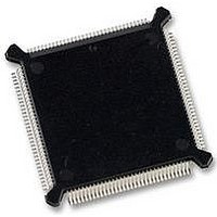
MC68331CEH25 Freescale Semiconductor, MC68331CEH25 Datasheet - Page 52

MC68331CEH25
Manufacturer Part Number
MC68331CEH25
Description
IC MCU 32BIT 25MHZ 132-PQFP
Manufacturer
Freescale Semiconductor
Series
M683xxr
Specifications of MC68331CEH25
Core Processor
CPU32
Core Size
32-Bit
Speed
25MHz
Connectivity
EBI/EMI, SCI, SPI, UART/USART
Peripherals
POR, PWM, WDT
Number Of I /o
18
Program Memory Type
ROMless
Voltage - Supply (vcc/vdd)
4.5 V ~ 5.5 V
Oscillator Type
Internal
Operating Temperature
-40°C ~ 85°C
Package / Case
132-QFP
Controller Family/series
68K
No. Of I/o's
18
Cpu Speed
25MHz
No. Of Timers
1
Embedded Interface Type
QSPI, SCI, UART
No. Of Pwm Channels
2
Digital Ic Case Style
PQFP
Rohs Compliant
Yes
Processor Series
M683xx
Core
CPU32
Data Bus Width
32 bit
Data Ram Size
80 B
Interface Type
QSPI, SCI, UART
Maximum Clock Frequency
25 MHz
Number Of Programmable I/os
18
Number Of Timers
1
Maximum Operating Temperature
+ 85 C
Mounting Style
SMD/SMT
Minimum Operating Temperature
- 40 C
Eeprom Size
-
Ram Size
-
Program Memory Size
-
Data Converters
-
Lead Free Status / Rohs Status
Details
Available stocks
Company
Part Number
Manufacturer
Quantity
Price
Company:
Part Number:
MC68331CEH25
Manufacturer:
PANASONIC
Quantity:
2 000
Company:
Part Number:
MC68331CEH25
Manufacturer:
Freescale Semiconductor
Quantity:
135
Company:
Part Number:
MC68331CEH25
Manufacturer:
Freescale Semiconductor
Quantity:
10 000
- Current page: 52 of 254
- Download datasheet (7Mb)
4
4.3.1 Clock Sources
4.3.2 Clock Synthesizer Operation
4-10
The state of the clock mode (MODCLK) pin during reset determines clock source.
When MODCLK is held high during reset, the clock synthesizer generates a clock sig-
nal from either an internal or an external reference frequency — the clock synthesizer
control register (SYNCR) determines operating frequency and mode of operation.
When MODCLK is held low during reset, the clock synthesizer is disabled and an ex-
ternal system clock signal must be applied — SYNCR control bits have no effect.
To generate a reference frequency using the internal oscillator a reference crystal
must be connected between the EXTAL and XTAL pins. Figure 4-5 shows a recom-
mended circuit.
If an external reference signal or an external system clock signal is applied via the EX-
TAL pin, the XTAL pin must be left floating. External reference signal frequency must
be less than or equal to maximum specified reference frequency. External system
clock signal frequency must be less than or equal to maximum specified system clock
frequency.
When an external system clock signal is applied (PLL disabled, MODCLK = 0 during
reset), the duty cycle of the input is critical, especially at operating frequencies close
to maximum. The relationship between clock signal duty cycle and clock signal period
is expressed:
V
erence frequency is applied. A separate power source increases MCU noise immunity
and can be used to run the clock when the MCU is powered down. A quiet power sup-
ply must be used as the V
be placed as close as possible to the V
DDSYN
*
Resistance and capacitance based on a test circuit constructed with a DAISHINKU DMX-38 32.768-kHz crystal.
Specific components must be based on crystal type. Contact crystal vendor for exact circuit.
is used to power the clock circuits when either an internal or an external ref-
=
----------------------------------------------------------------------------------------------------------------------------------------------------------------------
50% Percentage Variation of External Clock Input Duty Cycle
–
Figure 4-5 System Clock Oscillator Circuit
Freescale Semiconductor, Inc.
For More Information On This Product,
Minimum External Clock High Low Time
V
DDSYN
SYSTEM INTEGRATION MODULE
SSI
Minumum External Clock Period
22 pF
C1
22 pF
Go to: www.freescale.com
C2
*
*
source. Adequate external bypass capacitors should
330k
R1
DDSYN
10M
R2
pin to assure stable operating frequen-
EXTAL
XTAL
USER’S MANUAL
32 OSCILLATOR
MC68331
Related parts for MC68331CEH25
Image
Part Number
Description
Manufacturer
Datasheet
Request
R
Part Number:
Description:
Mc68331 32 Bit Microcontroller
Manufacturer:
Freescale Semiconductor, Inc
Datasheet:
Part Number:
Description:
Manufacturer:
Freescale Semiconductor, Inc
Datasheet:
Part Number:
Description:
Manufacturer:
Freescale Semiconductor, Inc
Datasheet:
Part Number:
Description:
Manufacturer:
Freescale Semiconductor, Inc
Datasheet:
Part Number:
Description:
Manufacturer:
Freescale Semiconductor, Inc
Datasheet:
Part Number:
Description:
Manufacturer:
Freescale Semiconductor, Inc
Datasheet:
Part Number:
Description:
Manufacturer:
Freescale Semiconductor, Inc
Datasheet:
Part Number:
Description:
Manufacturer:
Freescale Semiconductor, Inc
Datasheet:
Part Number:
Description:
Manufacturer:
Freescale Semiconductor, Inc
Datasheet:
Part Number:
Description:
Manufacturer:
Freescale Semiconductor, Inc
Datasheet:
Part Number:
Description:
Manufacturer:
Freescale Semiconductor, Inc
Datasheet:
Part Number:
Description:
Manufacturer:
Freescale Semiconductor, Inc
Datasheet:
Part Number:
Description:
Manufacturer:
Freescale Semiconductor, Inc
Datasheet:
Part Number:
Description:
Manufacturer:
Freescale Semiconductor, Inc
Datasheet:
Part Number:
Description:
Manufacturer:
Freescale Semiconductor, Inc
Datasheet:


