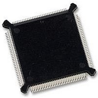
MC68331CEH25 Freescale Semiconductor, MC68331CEH25 Datasheet - Page 51

MC68331CEH25
Manufacturer Part Number
MC68331CEH25
Description
IC MCU 32BIT 25MHZ 132-PQFP
Manufacturer
Freescale Semiconductor
Series
M683xxr
Specifications of MC68331CEH25
Core Processor
CPU32
Core Size
32-Bit
Speed
25MHz
Connectivity
EBI/EMI, SCI, SPI, UART/USART
Peripherals
POR, PWM, WDT
Number Of I /o
18
Program Memory Type
ROMless
Voltage - Supply (vcc/vdd)
4.5 V ~ 5.5 V
Oscillator Type
Internal
Operating Temperature
-40°C ~ 85°C
Package / Case
132-QFP
Controller Family/series
68K
No. Of I/o's
18
Cpu Speed
25MHz
No. Of Timers
1
Embedded Interface Type
QSPI, SCI, UART
No. Of Pwm Channels
2
Digital Ic Case Style
PQFP
Rohs Compliant
Yes
Processor Series
M683xx
Core
CPU32
Data Bus Width
32 bit
Data Ram Size
80 B
Interface Type
QSPI, SCI, UART
Maximum Clock Frequency
25 MHz
Number Of Programmable I/os
18
Number Of Timers
1
Maximum Operating Temperature
+ 85 C
Mounting Style
SMD/SMT
Minimum Operating Temperature
- 40 C
Eeprom Size
-
Ram Size
-
Program Memory Size
-
Data Converters
-
Lead Free Status / Rohs Status
Details
Available stocks
Company
Part Number
Manufacturer
Quantity
Price
Company:
Part Number:
MC68331CEH25
Manufacturer:
PANASONIC
Quantity:
2 000
Company:
Part Number:
MC68331CEH25
Manufacturer:
Freescale Semiconductor
Quantity:
135
Company:
Part Number:
MC68331CEH25
Manufacturer:
Freescale Semiconductor
Quantity:
10 000
- Current page: 51 of 254
- Download datasheet (7Mb)
4.2.13 Freeze Operation
4.3 System Clock
MC68331
USER’S MANUAL
The FREEZE signal halts MCU operations during debugging. FREEZE is asserted in-
ternally by the CPU32 if a breakpoint occurs while background mode is enabled. When
FREEZE is asserted, only the bus monitor, software watchdog, and periodic interrupt
timer are affected. The halt monitor and spurious interrupt monitor continue to operate
normally. Setting the freeze bus monitor (FRZBM) bit in the SIMCR disables the bus
monitor when FREEZE is asserted, and setting the freeze software watchdog
(FRZSW) bit disables the software watchdog and the periodic interrupt timer when
FREEZE is asserted. When FRZSW is set, FREEZE assertion must be at least two
times the PIT clock source period to ensure an accurate number of PIT counts.
The system clock in the SIM provides timing signals for the IMB modules and for an
external peripheral bus. Because the MCU is a fully static design, register and memory
contents are not affected when the clock rate changes. System hardware and software
support changes in clock rate during operation.
The system clock signal can be generated in one of three ways. An internal phase-
locked loop can synthesize the clock from either an internal reference or an external
reference, or the clock signal can be input from an external frequency source. Keep
these clock sources in mind while reading the rest of this section. Figure 4-4 is a block
diagram of the system clock. Refer to APPENDIX A ELECTRICAL CHARACTERIS-
TICS for clock specifications.
EXTAL
OSCILLATOR
CRYSTAL
XTAL
Figure 4-4 System Clock Block Diagram
COMPARATOR
Freescale Semiconductor, Inc.
PHASE
For More Information On This Product,
SYSTEM INTEGRATION MODULE
Go to: www.freescale.com
SYSTEM CLOCK CONTROL
FEEDBACK DIVIDER
LOW-PASS
FILTER
XFC
W
Y
X
V
DDSYN
VCO
SYSTEM
CLOCK
CLKOUT
32 PLL BLOCK
4-9
4
Related parts for MC68331CEH25
Image
Part Number
Description
Manufacturer
Datasheet
Request
R
Part Number:
Description:
Mc68331 32 Bit Microcontroller
Manufacturer:
Freescale Semiconductor, Inc
Datasheet:
Part Number:
Description:
Manufacturer:
Freescale Semiconductor, Inc
Datasheet:
Part Number:
Description:
Manufacturer:
Freescale Semiconductor, Inc
Datasheet:
Part Number:
Description:
Manufacturer:
Freescale Semiconductor, Inc
Datasheet:
Part Number:
Description:
Manufacturer:
Freescale Semiconductor, Inc
Datasheet:
Part Number:
Description:
Manufacturer:
Freescale Semiconductor, Inc
Datasheet:
Part Number:
Description:
Manufacturer:
Freescale Semiconductor, Inc
Datasheet:
Part Number:
Description:
Manufacturer:
Freescale Semiconductor, Inc
Datasheet:
Part Number:
Description:
Manufacturer:
Freescale Semiconductor, Inc
Datasheet:
Part Number:
Description:
Manufacturer:
Freescale Semiconductor, Inc
Datasheet:
Part Number:
Description:
Manufacturer:
Freescale Semiconductor, Inc
Datasheet:
Part Number:
Description:
Manufacturer:
Freescale Semiconductor, Inc
Datasheet:
Part Number:
Description:
Manufacturer:
Freescale Semiconductor, Inc
Datasheet:
Part Number:
Description:
Manufacturer:
Freescale Semiconductor, Inc
Datasheet:
Part Number:
Description:
Manufacturer:
Freescale Semiconductor, Inc
Datasheet:


