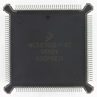
MC68302EH16C Freescale Semiconductor, MC68302EH16C Datasheet - Page 39

MC68302EH16C
Manufacturer Part Number
MC68302EH16C
Description
IC MPU MULTI-PROTOCOL 132-PQFP
Manufacturer
Freescale Semiconductor
Datasheets
1.MC68302AG20C.pdf
(4 pages)
2.MC68302AG20C.pdf
(2 pages)
3.MC68302AG20C.pdf
(13 pages)
4.MC68302EH16C.pdf
(481 pages)
Specifications of MC68302EH16C
Processor Type
M683xx 32-Bit
Speed
16MHz
Voltage
5V
Mounting Type
Surface Mount
Package / Case
132-MQFP, 132-PQFP
Controller Family/series
68K
Core Size
32 Bit
Ram Memory Size
1152Byte
Cpu Speed
16MHz
No. Of Timers
3
Embedded Interface Type
SCP, TDM
Digital Ic Case Style
PQFP
Rohs Compliant
Yes
Family Name
M68000
Device Core
ColdFire
Device Core Size
32b
Frequency (max)
16MHz
Instruction Set Architecture
RISC
Supply Voltage 1 (typ)
5V
Operating Temp Range
0C to 70C
Operating Temperature Classification
Commercial
Mounting
Surface Mount
Pin Count
132
Package Type
PQFP
Lead Free Status / RoHS Status
Lead free / RoHS Compliant
Features
-
Lead Free Status / Rohs Status
RoHS Compliant part
Electrostatic Device
Available stocks
Company
Part Number
Manufacturer
Quantity
Price
Company:
Part Number:
MC68302EH16C
Manufacturer:
Freescale Semiconductor
Quantity:
135
Company:
Part Number:
MC68302EH16C
Manufacturer:
PANA
Quantity:
99
Company:
Part Number:
MC68302EH16C
Manufacturer:
Freescale Semiconductor
Quantity:
10 000
Part Number:
MC68302EH16C
Manufacturer:
FREESCALE
Quantity:
20 000
Company:
Part Number:
MC68302EH16CB1
Manufacturer:
Freescale Semiconductor
Quantity:
10 000
Company:
Part Number:
MC68302EH16CR2
Manufacturer:
Freescale Semiconductor
Quantity:
10 000
- MC68302AG20C PDF datasheet
- MC68302AG20C PDF datasheet #2
- MC68302AG20C PDF datasheet #3
- MC68302EH16C PDF datasheet #4
- Current page: 39 of 481
- Download datasheet (2Mb)
2.4.2 Exception Stacking Order
Exception processing saves the most volatile portion of the current processor context on top
of the supervisor stack. This context is organized in a format called the exception stack
frame. The amount and type of information saved on the stack is determined by the type of
exception. The reset exception causes the M68000 to halt current execution and to read a
new SSP and PC as shown in Table 2-5. A bus error or address error causes the M68000
to store the information shown in Figure 2-3. The interrupts, traps, illegal instructions, and
trace stack frames are shown in Figure 2-4.
MOTOROLA
NOTES:
1. Vector numbers 12–14, 16–23, and 48–63 are reserved for future enhancements by Motorola
2. Unlike the other vectors which only require two words, reset vector (0) requires four words and is
3. The spurious interrupt vector is taken when there is a bus error indication during interrupt
4. TRAP # n uses vector number 32 + n.
16–23 1
48–63 1
64–255
32–47
(with vectors 60–63 being used by the M68302 (see 2.7 MC68302 IMP Configuration and
Control)). No user peripheral devices should be assigned these numbers.
located in the supervisor program space.
processing.
12 1
13 1
14 1
11
15
24
25
26
27
28
29
30
31
Table 2-5. M68000 Exception Vector Assignment
1020
100
104
108
112
116
120
124
128
188
192
255
256
44
48
52
56
60
64
92
96
MC68302 USER’S MANUAL
0BC
0FC
3FC
02C
03C
05C
06C
07C
0C0
030
034
038
040
060
064
068
070
074
078
080
100
SD
SD
SD
SD
SD
SD
SD
SD
SD
SD
SD
SD
SD
SD
SD
SD
SD
SD
SD
SD
SD
Line 1111 Emulator
(Unassigned, Reserved)
(Unassigned, Reserved)
(Unassigned, Reserved)
Uninitialized Interrupt Vector
(Unassigned, Reserved)
Spurious Interrupt 3
Level 1 Interrupt Autovector
Level 2 Interrupt Autovector
Level 3 Interrupt Autovector
Level 4 Interrupt Autovector
Level 5 Interrupt Autovector
Level 6 Interrupt Autovector
Level 7 Interrupt Autovector
TRAP Instruction Vectors 4
(Unassigned, Reserved)
User Interrupt Vectors
MC68000/MC68008 Core
2-9
Related parts for MC68302EH16C
Image
Part Number
Description
Manufacturer
Datasheet
Request
R
Part Number:
Description:
Manufacturer:
Freescale Semiconductor, Inc
Datasheet:

Part Number:
Description:
MC68302 Configuring the Chip Selects on the MC68302
Manufacturer:
Motorola / Freescale Semiconductor

Part Number:
Description:
MC68302 Design Concept - Expanding Interrupts on the MC68302
Manufacturer:
Motorola / Freescale Semiconductor

Part Number:
Description:
MC68302 MC68302 Adapting a WAN Controller to a LAN Environment
Manufacturer:
Motorola / Freescale Semiconductor

Part Number:
Description:
MC68302 EKB Applications - Power Measurements on the MC68302
Manufacturer:
Motorola / Freescale Semiconductor

Part Number:
Description:
MC68302 Interfacing the MC68020 to a Slave MC68302
Manufacturer:
Motorola / Freescale Semiconductor

Part Number:
Description:
MC68302 MC68302 Software Performance
Manufacturer:
Motorola / Freescale Semiconductor

Part Number:
Description:
MC68302 Evaluating EDX on the ADS302
Manufacturer:
Motorola / Freescale Semiconductor

Part Number:
Description:
MC68302 Design Advisory #1 - MC68SC302 Passive ISDN Protocol Engine
Manufacturer:
Motorola / Freescale Semiconductor

Part Number:
Description:
MC68302, MC68360, and MPC860 Characteristics and Design Notes for Crystal Feedback Oscillators
Manufacturer:
Motorola / Freescale Semiconductor
Part Number:
Description:
Mc68302 Integrated Multi-protocol Processor
Manufacturer:
Freescale Semiconductor, Inc
Datasheet:
Part Number:
Description:
Manufacturer:
Freescale Semiconductor, Inc
Datasheet:
Part Number:
Description:
Manufacturer:
Freescale Semiconductor, Inc
Datasheet:
Part Number:
Description:
Manufacturer:
Freescale Semiconductor, Inc
Datasheet:
Part Number:
Description:
Manufacturer:
Freescale Semiconductor, Inc
Datasheet:


