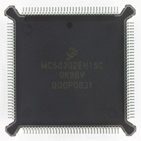
MC68302EH16C Freescale Semiconductor, MC68302EH16C Datasheet - Page 163

MC68302EH16C
Manufacturer Part Number
MC68302EH16C
Description
IC MPU MULTI-PROTOCOL 132-PQFP
Manufacturer
Freescale Semiconductor
Datasheets
1.MC68302AG20C.pdf
(4 pages)
2.MC68302AG20C.pdf
(2 pages)
3.MC68302AG20C.pdf
(13 pages)
4.MC68302EH16C.pdf
(481 pages)
Specifications of MC68302EH16C
Processor Type
M683xx 32-Bit
Speed
16MHz
Voltage
5V
Mounting Type
Surface Mount
Package / Case
132-MQFP, 132-PQFP
Controller Family/series
68K
Core Size
32 Bit
Ram Memory Size
1152Byte
Cpu Speed
16MHz
No. Of Timers
3
Embedded Interface Type
SCP, TDM
Digital Ic Case Style
PQFP
Rohs Compliant
Yes
Family Name
M68000
Device Core
ColdFire
Device Core Size
32b
Frequency (max)
16MHz
Instruction Set Architecture
RISC
Supply Voltage 1 (typ)
5V
Operating Temp Range
0C to 70C
Operating Temperature Classification
Commercial
Mounting
Surface Mount
Pin Count
132
Package Type
PQFP
Lead Free Status / RoHS Status
Lead free / RoHS Compliant
Features
-
Lead Free Status / Rohs Status
RoHS Compliant part
Electrostatic Device
Available stocks
Company
Part Number
Manufacturer
Quantity
Price
Company:
Part Number:
MC68302EH16C
Manufacturer:
Freescale Semiconductor
Quantity:
135
Company:
Part Number:
MC68302EH16C
Manufacturer:
PANA
Quantity:
99
Company:
Part Number:
MC68302EH16C
Manufacturer:
Freescale Semiconductor
Quantity:
10 000
Part Number:
MC68302EH16C
Manufacturer:
FREESCALE
Quantity:
20 000
Company:
Part Number:
MC68302EH16CB1
Manufacturer:
Freescale Semiconductor
Quantity:
10 000
Company:
Part Number:
MC68302EH16CR2
Manufacturer:
Freescale Semiconductor
Quantity:
10 000
- MC68302AG20C PDF datasheet
- MC68302AG20C PDF datasheet #2
- MC68302AG20C PDF datasheet #3
- MC68302EH16C PDF datasheet #4
- Current page: 163 of 481
- Download datasheet (2Mb)
The SCC should be disabled and re-enabled if any change is made to the SCC's parallel
I/O or serial channels physical interface configuration. The SCC does not need to be dis-
abled if only a change to a parameter RAM value is made. See 4.5.6 SCC Parameter RAM
Memory Map for a discussion of when parameter RAM values may be modified.
To save power, the SCCs may simply be disabled. Clearing the enable transmitter (ENT) bit
in the SCC mode register causes the SCC transmitter to consume the least possible power;
clearing the ENR bit causes a similar action for the SCC receiver.
The above statement on saving power is independent of a decision to use the low-power
modes (see 3.8 System Control). If a low-power mode is desired, the SCC may be disabled
before entering the low-power mode, or it may be left enabled so that an SCC interrupt may
bring the IMP out of the low-power mode. One common use of the low-power mode is to
disable the transmitter but leave the receiver enabled (i.e., in the hunt mode) so that an ar-
riving frame destined for this station will cause an interrupt, waking the IMP from its low-pow-
er mode.
The low-power mode affects the M68000 core, not the SCCs. Since the SCCs are usually
clocked at a far lower rate than the M68000 core, significant power savings may still be
achieved with the SCCs fully enabled and the M68000 core in the low-power mode.
4.5.11 UART Controller
Many applications need a simple method of communicating low-speed data between equip-
ment. The universal asynchronous receiver transmitter (UART) protocol is the de-facto stan-
dard for such communications. The term asynchronous is used because it is not necessary
to send clocking information with the data that is sent. UART links are typically 38400 baud
or less in speed and are character oriented (i.e., the smallest unit of data that can be cor-
rectly received or transmitted is a character). Typical applications of asynchronous links are
connections between terminals and computer equipment. Even in applications where syn-
chronous communication is required, the UART is often used for a local debugging port to
run board debugger software. The character format of the UART protocol is shown in Figure
4-17.
MOTOROLA
UART TCLK
UART TXD
16
START
BIT
Figure 4-17. UART Frame Format
MC68302 USER’S MANUAL
LEAST SIGNIFICANT BIT FIRST
7 OR 8 DATA BITS WITH THE
Communications Processor (CP)
ADDR.
OPTIONAL
BIT
PAR.
BIT
9/16 TO 2
STOP BITS
4-43
Related parts for MC68302EH16C
Image
Part Number
Description
Manufacturer
Datasheet
Request
R
Part Number:
Description:
Manufacturer:
Freescale Semiconductor, Inc
Datasheet:

Part Number:
Description:
MC68302 Configuring the Chip Selects on the MC68302
Manufacturer:
Motorola / Freescale Semiconductor

Part Number:
Description:
MC68302 Design Concept - Expanding Interrupts on the MC68302
Manufacturer:
Motorola / Freescale Semiconductor

Part Number:
Description:
MC68302 MC68302 Adapting a WAN Controller to a LAN Environment
Manufacturer:
Motorola / Freescale Semiconductor

Part Number:
Description:
MC68302 EKB Applications - Power Measurements on the MC68302
Manufacturer:
Motorola / Freescale Semiconductor

Part Number:
Description:
MC68302 Interfacing the MC68020 to a Slave MC68302
Manufacturer:
Motorola / Freescale Semiconductor

Part Number:
Description:
MC68302 MC68302 Software Performance
Manufacturer:
Motorola / Freescale Semiconductor

Part Number:
Description:
MC68302 Evaluating EDX on the ADS302
Manufacturer:
Motorola / Freescale Semiconductor

Part Number:
Description:
MC68302 Design Advisory #1 - MC68SC302 Passive ISDN Protocol Engine
Manufacturer:
Motorola / Freescale Semiconductor

Part Number:
Description:
MC68302, MC68360, and MPC860 Characteristics and Design Notes for Crystal Feedback Oscillators
Manufacturer:
Motorola / Freescale Semiconductor
Part Number:
Description:
Mc68302 Integrated Multi-protocol Processor
Manufacturer:
Freescale Semiconductor, Inc
Datasheet:
Part Number:
Description:
Manufacturer:
Freescale Semiconductor, Inc
Datasheet:
Part Number:
Description:
Manufacturer:
Freescale Semiconductor, Inc
Datasheet:
Part Number:
Description:
Manufacturer:
Freescale Semiconductor, Inc
Datasheet:
Part Number:
Description:
Manufacturer:
Freescale Semiconductor, Inc
Datasheet:


