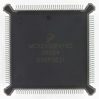
MC68302EH16C Freescale Semiconductor, MC68302EH16C Datasheet - Page 136

MC68302EH16C
Manufacturer Part Number
MC68302EH16C
Description
IC MPU MULTI-PROTOCOL 132-PQFP
Manufacturer
Freescale Semiconductor
Datasheets
1.MC68302AG20C.pdf
(4 pages)
2.MC68302AG20C.pdf
(2 pages)
3.MC68302AG20C.pdf
(13 pages)
4.MC68302EH16C.pdf
(481 pages)
Specifications of MC68302EH16C
Processor Type
M683xx 32-Bit
Speed
16MHz
Voltage
5V
Mounting Type
Surface Mount
Package / Case
132-MQFP, 132-PQFP
Controller Family/series
68K
Core Size
32 Bit
Ram Memory Size
1152Byte
Cpu Speed
16MHz
No. Of Timers
3
Embedded Interface Type
SCP, TDM
Digital Ic Case Style
PQFP
Rohs Compliant
Yes
Family Name
M68000
Device Core
ColdFire
Device Core Size
32b
Frequency (max)
16MHz
Instruction Set Architecture
RISC
Supply Voltage 1 (typ)
5V
Operating Temp Range
0C to 70C
Operating Temperature Classification
Commercial
Mounting
Surface Mount
Pin Count
132
Package Type
PQFP
Lead Free Status / RoHS Status
Lead free / RoHS Compliant
Features
-
Lead Free Status / Rohs Status
RoHS Compliant part
Electrostatic Device
Available stocks
Company
Part Number
Manufacturer
Quantity
Price
Company:
Part Number:
MC68302EH16C
Manufacturer:
Freescale Semiconductor
Quantity:
135
Company:
Part Number:
MC68302EH16C
Manufacturer:
PANA
Quantity:
99
Company:
Part Number:
MC68302EH16C
Manufacturer:
Freescale Semiconductor
Quantity:
10 000
Part Number:
MC68302EH16C
Manufacturer:
FREESCALE
Quantity:
20 000
Company:
Part Number:
MC68302EH16CB1
Manufacturer:
Freescale Semiconductor
Quantity:
10 000
Company:
Part Number:
MC68302EH16CR2
Manufacturer:
Freescale Semiconductor
Quantity:
10 000
- MC68302AG20C PDF datasheet
- MC68302AG20C PDF datasheet #2
- MC68302AG20C PDF datasheet #3
- MC68302EH16C PDF datasheet #4
- Current page: 136 of 481
- Download datasheet (2Mb)
Communications Processor (CP)
The monitor channel is used to transfer data between layer-1 devices and the control unit
(i.e., the M68000 core). The command/indication channel is used to control activation/deac-
tivation procedures or for the switching of test loops by the control unit.
The IMP supports all five channels of the GCI channel 0. The following table shows where
each channel can be routed. The two B channels can be concatenated and routed to the
same SCC channel.
The GCI interface supports the CCITT I.460 recommendation for data rate adaptation. The
GCI interface can access each bit of the B channel as an 8-kbps channel. The mask register
(SIMASK) for the B channels specifies which bits are supported by the GCI interface. The
receiver will receive only the bits that are enabled by SIMASK; the transmitter will transmit
only the bits that are enabled by SIMASK and will not drive the L1TXD pin otherwise (L1TXD
in GCI mode is an open-drain output).
The IMP supports contention detection on the D channel. When the IMP has data to transmit
on the D channel, it checks bit 4 of the SCIT C/I channel 2. The physical layer device mon-
itors the physical layer bus for activity on the D channel and indicates with this bit that the
channel is free. If a collision is detected on the D channel, the physical layer device sets bit
4 of C/I channel 2 to logic high. The IMP then aborts its transmission and retransmits the
frame when this bit is asserted again. This procedure is handled automatically for the first
two buffers of a frame. The L1GR line may also be used for access to the S interface D chan-
nel. This signal is checked by the IMP, and the physical layer device should indicate that the
S interface D channel is free by asserting L1GR.
In the deactivated state, the clock pulse is disabled, and the data line is a logic one. The
layer-1 device activates the IMP by enabling the clock pulses and by an indication in the
channel 0 C/I channel. The IMP will then report to the M68000 core by a maskable interrupt
that a valid indication is in the SMC2 receive buffer descriptor.
When the M68000 core activates the line, it sets SETZ in the serial interface mode (SIMO-
DE) register, causing the data output from L1TXD to become a logic zero. Code 0 (com-
mand timing TIM) will be transmitted on channel 0 C/I channel to the layer-1 device until the
SETZ is reset. The physical layer device will resume transmitting the clock pulses and will
give an indication in the channel 0 C/I channel. The M68000 core should reset SETZ to en-
able data output.
4.4.3 PCM Highway Mode
In PCM highway mode, one, two, or all three SCCs can be multiplexed together to support
various time-division multiplexed interfaces. PCM highway supports the standard T1 and
CEPT interfaces as well as user-defined interfaces. In this mode, the NMSI1 pins have new
names and functions (see Table 4-2).
4-16
GCI Channel 0
MC68302 USER’S MANUAL
C/I
B1
B2
D
M
SCC1, SCC2, SCC3
SCC1, SCC2, SCC3
SCC1, SCC2, SCC3
SMC1
SMC2
Serial Controllers
MOTOROLA
Related parts for MC68302EH16C
Image
Part Number
Description
Manufacturer
Datasheet
Request
R
Part Number:
Description:
Manufacturer:
Freescale Semiconductor, Inc
Datasheet:

Part Number:
Description:
MC68302 Configuring the Chip Selects on the MC68302
Manufacturer:
Motorola / Freescale Semiconductor

Part Number:
Description:
MC68302 Design Concept - Expanding Interrupts on the MC68302
Manufacturer:
Motorola / Freescale Semiconductor

Part Number:
Description:
MC68302 MC68302 Adapting a WAN Controller to a LAN Environment
Manufacturer:
Motorola / Freescale Semiconductor

Part Number:
Description:
MC68302 EKB Applications - Power Measurements on the MC68302
Manufacturer:
Motorola / Freescale Semiconductor

Part Number:
Description:
MC68302 Interfacing the MC68020 to a Slave MC68302
Manufacturer:
Motorola / Freescale Semiconductor

Part Number:
Description:
MC68302 MC68302 Software Performance
Manufacturer:
Motorola / Freescale Semiconductor

Part Number:
Description:
MC68302 Evaluating EDX on the ADS302
Manufacturer:
Motorola / Freescale Semiconductor

Part Number:
Description:
MC68302 Design Advisory #1 - MC68SC302 Passive ISDN Protocol Engine
Manufacturer:
Motorola / Freescale Semiconductor

Part Number:
Description:
MC68302, MC68360, and MPC860 Characteristics and Design Notes for Crystal Feedback Oscillators
Manufacturer:
Motorola / Freescale Semiconductor
Part Number:
Description:
Mc68302 Integrated Multi-protocol Processor
Manufacturer:
Freescale Semiconductor, Inc
Datasheet:
Part Number:
Description:
Manufacturer:
Freescale Semiconductor, Inc
Datasheet:
Part Number:
Description:
Manufacturer:
Freescale Semiconductor, Inc
Datasheet:
Part Number:
Description:
Manufacturer:
Freescale Semiconductor, Inc
Datasheet:
Part Number:
Description:
Manufacturer:
Freescale Semiconductor, Inc
Datasheet:


