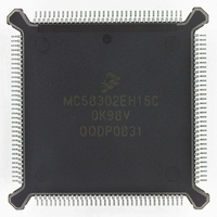
MC68302EH16C Freescale Semiconductor, MC68302EH16C Datasheet - Page 127

MC68302EH16C
Manufacturer Part Number
MC68302EH16C
Description
IC MPU MULTI-PROTOCOL 132-PQFP
Manufacturer
Freescale Semiconductor
Datasheets
1.MC68302AG20C.pdf
(4 pages)
2.MC68302AG20C.pdf
(2 pages)
3.MC68302AG20C.pdf
(13 pages)
4.MC68302EH16C.pdf
(481 pages)
Specifications of MC68302EH16C
Processor Type
M683xx 32-Bit
Speed
16MHz
Voltage
5V
Mounting Type
Surface Mount
Package / Case
132-MQFP, 132-PQFP
Controller Family/series
68K
Core Size
32 Bit
Ram Memory Size
1152Byte
Cpu Speed
16MHz
No. Of Timers
3
Embedded Interface Type
SCP, TDM
Digital Ic Case Style
PQFP
Rohs Compliant
Yes
Family Name
M68000
Device Core
ColdFire
Device Core Size
32b
Frequency (max)
16MHz
Instruction Set Architecture
RISC
Supply Voltage 1 (typ)
5V
Operating Temp Range
0C to 70C
Operating Temperature Classification
Commercial
Mounting
Surface Mount
Pin Count
132
Package Type
PQFP
Lead Free Status / RoHS Status
Lead free / RoHS Compliant
Features
-
Lead Free Status / Rohs Status
RoHS Compliant part
Electrostatic Device
Available stocks
Company
Part Number
Manufacturer
Quantity
Price
Company:
Part Number:
MC68302EH16C
Manufacturer:
Freescale Semiconductor
Quantity:
135
Company:
Part Number:
MC68302EH16C
Manufacturer:
PANA
Quantity:
99
Company:
Part Number:
MC68302EH16C
Manufacturer:
Freescale Semiconductor
Quantity:
10 000
Part Number:
MC68302EH16C
Manufacturer:
FREESCALE
Quantity:
20 000
Company:
Part Number:
MC68302EH16CB1
Manufacturer:
Freescale Semiconductor
Quantity:
10 000
Company:
Part Number:
MC68302EH16CR2
Manufacturer:
Freescale Semiconductor
Quantity:
10 000
- MC68302AG20C PDF datasheet
- MC68302AG20C PDF datasheet #2
- MC68302AG20C PDF datasheet #3
- MC68302EH16C PDF datasheet #4
- Current page: 127 of 481
- Download datasheet (2Mb)
FLG—Command Semaphore Flag
4.3.1 Command Execution Latency
Commands are executed at a priority higher than the SCCs, but less than the priority of the
DRAM refresh controller. The longest command, the ENTER HUNT MODE command, ex-
ecutes in 41 clocks. All other commands execute in less than 20 clocks. The maximum com-
mand latency is calculated as follows:
For example, if HDLC and UART modes are used on the SCCs with the DRAM refresh con-
troller operating, the maximum command latency is 41 + 25 + 165 = 231 clocks = 13 s at
16.67 MHz. The equations assume that the DRAM refresh cycle occurs once during the
command latency. Note that commands are typically given only in special error-handling sit-
uations and that the typical latency is much less than the worst case value.
4.4 SERIAL CHANNELS PHYSICAL INTERFACE
The serial channels physical interface joins the physical layer serial lines to the three SCCs
and the two SMCs. (The separate three-wire SCP interface is described in 4.6 Serial Com-
munication Port (SCP).)
The MC68302 supports four different external physical interfaces from the SCCs:
The most generic physical interface on the MC68302 is the nonmultiplexed serial interface
(NMSI). The NMSI consists of seven of the basic modem (or RS-232) signals: TXD, TCLK,
RXD, RCLK, RTS, CTS, and CD. Each SCC can have its own set of NMSI signals as shown
in Figure 4-3. In addition to the NMSI, the baud rate generator clocks may be output on sep-
arate BRG pins as shown. All NMSI2 pins are multiplexed with parallel I/O pins. The user
may choose which NMSI2 pins are used by the SCC2 and which are used as parallel I/O.
On NMSI3, the TXD, TCLK, RXD, and RCLK pins are multiplexed with parallel I/O lines;
MOTOROLA
The bit is set by the M68000 core and cleared by the CP.
• Command execution time (41 or 20) +
• 25 clocks if DRAM refresh controller is used +
1. NMSI—Nonmultiplexed Serial Interface
2. PCM—Pulse Code Modulation Highway
3. IDL—Interchip Digital Link
4. GCI—General Circuit Interface
0 = The CP is ready to receive a new command.
1 = The CR contains a command that the CP is currently processing. The CP clears
—205 clocks if any SCC is enabled with BISYNC; or
—165 clocks if any SCC is enabled with Transparent; or
—165 clocks if any SCC is enabled with HDLC; or
—150 clocks if any SCC is enabled with UART; or
—140 clocks if any SCC is enabled with DDCMP; else
—0
this bit at the end of command execution. Note that the execution of the STOP
TRANSMIT or RESTART TRANSMIT commands may not affect the TXD pin until
many clocks after the FLG bit is cleared by the CP due to the transmit FIFO latency.
MC68302 USER’S MANUAL
Communications Processor (CP)
4-7
Related parts for MC68302EH16C
Image
Part Number
Description
Manufacturer
Datasheet
Request
R
Part Number:
Description:
Manufacturer:
Freescale Semiconductor, Inc
Datasheet:

Part Number:
Description:
MC68302 Configuring the Chip Selects on the MC68302
Manufacturer:
Motorola / Freescale Semiconductor

Part Number:
Description:
MC68302 Design Concept - Expanding Interrupts on the MC68302
Manufacturer:
Motorola / Freescale Semiconductor

Part Number:
Description:
MC68302 MC68302 Adapting a WAN Controller to a LAN Environment
Manufacturer:
Motorola / Freescale Semiconductor

Part Number:
Description:
MC68302 EKB Applications - Power Measurements on the MC68302
Manufacturer:
Motorola / Freescale Semiconductor

Part Number:
Description:
MC68302 Interfacing the MC68020 to a Slave MC68302
Manufacturer:
Motorola / Freescale Semiconductor

Part Number:
Description:
MC68302 MC68302 Software Performance
Manufacturer:
Motorola / Freescale Semiconductor

Part Number:
Description:
MC68302 Evaluating EDX on the ADS302
Manufacturer:
Motorola / Freescale Semiconductor

Part Number:
Description:
MC68302 Design Advisory #1 - MC68SC302 Passive ISDN Protocol Engine
Manufacturer:
Motorola / Freescale Semiconductor

Part Number:
Description:
MC68302, MC68360, and MPC860 Characteristics and Design Notes for Crystal Feedback Oscillators
Manufacturer:
Motorola / Freescale Semiconductor
Part Number:
Description:
Mc68302 Integrated Multi-protocol Processor
Manufacturer:
Freescale Semiconductor, Inc
Datasheet:
Part Number:
Description:
Manufacturer:
Freescale Semiconductor, Inc
Datasheet:
Part Number:
Description:
Manufacturer:
Freescale Semiconductor, Inc
Datasheet:
Part Number:
Description:
Manufacturer:
Freescale Semiconductor, Inc
Datasheet:
Part Number:
Description:
Manufacturer:
Freescale Semiconductor, Inc
Datasheet:


