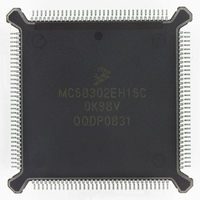
MC68302EH16C Freescale Semiconductor, MC68302EH16C Datasheet - Page 186

MC68302EH16C
Manufacturer Part Number
MC68302EH16C
Description
IC MPU MULTI-PROTOCOL 132-PQFP
Manufacturer
Freescale Semiconductor
Datasheets
1.MC68302AG20C.pdf
(4 pages)
2.MC68302AG20C.pdf
(2 pages)
3.MC68302AG20C.pdf
(13 pages)
4.MC68302EH16C.pdf
(481 pages)
Specifications of MC68302EH16C
Processor Type
M683xx 32-Bit
Speed
16MHz
Voltage
5V
Mounting Type
Surface Mount
Package / Case
132-MQFP, 132-PQFP
Controller Family/series
68K
Core Size
32 Bit
Ram Memory Size
1152Byte
Cpu Speed
16MHz
No. Of Timers
3
Embedded Interface Type
SCP, TDM
Digital Ic Case Style
PQFP
Rohs Compliant
Yes
Family Name
M68000
Device Core
ColdFire
Device Core Size
32b
Frequency (max)
16MHz
Instruction Set Architecture
RISC
Supply Voltage 1 (typ)
5V
Operating Temp Range
0C to 70C
Operating Temperature Classification
Commercial
Mounting
Surface Mount
Pin Count
132
Package Type
PQFP
Lead Free Status / RoHS Status
Lead free / RoHS Compliant
Features
-
Lead Free Status / Rohs Status
RoHS Compliant part
Electrostatic Device
Available stocks
Company
Part Number
Manufacturer
Quantity
Price
Company:
Part Number:
MC68302EH16C
Manufacturer:
Freescale Semiconductor
Quantity:
135
Company:
Part Number:
MC68302EH16C
Manufacturer:
PANA
Quantity:
99
Company:
Part Number:
MC68302EH16C
Manufacturer:
Freescale Semiconductor
Quantity:
10 000
Part Number:
MC68302EH16C
Manufacturer:
FREESCALE
Quantity:
20 000
Company:
Part Number:
MC68302EH16CB1
Manufacturer:
Freescale Semiconductor
Quantity:
10 000
Company:
Part Number:
MC68302EH16CR2
Manufacturer:
Freescale Semiconductor
Quantity:
10 000
- MC68302AG20C PDF datasheet
- MC68302AG20C PDF datasheet #2
- MC68302AG20C PDF datasheet #3
- MC68302EH16C PDF datasheet #4
- Current page: 186 of 481
- Download datasheet (2Mb)
Communications Processor (CP)
Three characters should first be entered into the UART control character table:
To receive the S records, the M68000 core must only wait for the RX interrupt, indicating the
reception of a complete S-record buffer. Transmission requires assembling S records into
data buffers and linking them to the transmit buffer table (transmission may be temporarily
halted by reception of an XOFF character). This scheme minimizes the number of interrupts
received by the M68000 core (one per S record) and relieves it from the task of continually
scanning for control characters.
4.5.12 HDLC Controller
Layer 2 of the seven-layer OSI model is the data link layer. One of the most common layer
2 protocols is HDLC. Many other common layer 2 protocols are heavily based on HDLC, par-
ticularly its framing structure: namely, SDLC, SS#7, LAPB, and LAPD. The framing structure
of HDLC is shown in Figure 4-24.
HDLC uses a zero insertion/deletion process (commonly known as bit-stuffing) to ensure
that the bit pattern of the delimiter flag does not occur in the fields between flags. The HDLC
frame is synchronous and therefore relies on the physical layer to provide a method of clock-
ing and synchronizing the transmitter and receiver.
Since the layer 2 frame can be transmitted over a point-to-point link, a broadcast network,
or packet and circuit-switched systems, an address field is needed to carry the frame's des-
tination address. The length of this field is commonly 0, 8, or 16 bits, depending on the data
link layer protocol. For instance, SDLC and LAPB use an 8-bit address. SS#7 has no ad-
dress field at all because it is always used in point-to-point signaling links. LAPD further di-
vides its 16-bit address into different fields to specify various access points within one piece
of equipment. It also defines a broadcast address. Some HDLC-type protocols also allow for
extended addressing beyond 16-bits.
4-66
1. End of Line—The empty (E) bit is cleared; the reject (R) bit is cleared. When an end-
2. XOFF—E should be cleared and R should be set. Whenever the M68000 core re-
3. XON—XON should be received after XOFF. E should be cleared and R should be set.
OPENING
8 BITS
FLAG
of-line character is received, the current buffer is closed (the next BD taken by the IMP)
and made available to the M68000 core for processing. This buffer contains an entire
S record, which the processor can now check and copy to memory or disk as required.
ceives a control character received interrupt and the receive control character register
contains XOFF, the software should immediately stop transmitting to the other station
by setting the FRZ bit in the UART mode register. This prevents data from being lost
by the other station when it runs out of receive buffers.
The FRZ bit on the transmitter should now be cleared. The IMP automatically resumes
transmission of the serial line at the point at which it was previously stopped. Like
XOFF, the XON character is not stored in the receive buffer.
ADDRESS
16 BITS
Figure 4-24. Typical HDLC Frame
MC68302 USER’S MANUAL
CONTROL
8 BITS
INFORMATION
(OPTIONAL)
8N BITS
16 BITS
CRC
MOTOROLA
CLOSING
8 BITS
FLAG
Related parts for MC68302EH16C
Image
Part Number
Description
Manufacturer
Datasheet
Request
R
Part Number:
Description:
Manufacturer:
Freescale Semiconductor, Inc
Datasheet:

Part Number:
Description:
MC68302 Configuring the Chip Selects on the MC68302
Manufacturer:
Motorola / Freescale Semiconductor

Part Number:
Description:
MC68302 Design Concept - Expanding Interrupts on the MC68302
Manufacturer:
Motorola / Freescale Semiconductor

Part Number:
Description:
MC68302 MC68302 Adapting a WAN Controller to a LAN Environment
Manufacturer:
Motorola / Freescale Semiconductor

Part Number:
Description:
MC68302 EKB Applications - Power Measurements on the MC68302
Manufacturer:
Motorola / Freescale Semiconductor

Part Number:
Description:
MC68302 Interfacing the MC68020 to a Slave MC68302
Manufacturer:
Motorola / Freescale Semiconductor

Part Number:
Description:
MC68302 MC68302 Software Performance
Manufacturer:
Motorola / Freescale Semiconductor

Part Number:
Description:
MC68302 Evaluating EDX on the ADS302
Manufacturer:
Motorola / Freescale Semiconductor

Part Number:
Description:
MC68302 Design Advisory #1 - MC68SC302 Passive ISDN Protocol Engine
Manufacturer:
Motorola / Freescale Semiconductor

Part Number:
Description:
MC68302, MC68360, and MPC860 Characteristics and Design Notes for Crystal Feedback Oscillators
Manufacturer:
Motorola / Freescale Semiconductor
Part Number:
Description:
Mc68302 Integrated Multi-protocol Processor
Manufacturer:
Freescale Semiconductor, Inc
Datasheet:
Part Number:
Description:
Manufacturer:
Freescale Semiconductor, Inc
Datasheet:
Part Number:
Description:
Manufacturer:
Freescale Semiconductor, Inc
Datasheet:
Part Number:
Description:
Manufacturer:
Freescale Semiconductor, Inc
Datasheet:
Part Number:
Description:
Manufacturer:
Freescale Semiconductor, Inc
Datasheet:


