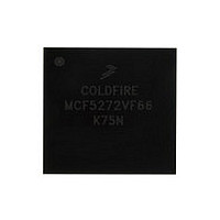
MCF5272VF66 Freescale, MCF5272VF66 Datasheet - Page 86

MCF5272VF66
Manufacturer Part Number
MCF5272VF66
Description
Manufacturer
Freescale
Datasheet
1.MCF5272VF66.pdf
(544 pages)
Specifications of MCF5272VF66
Family Name
MCF5xxx
Device Core
ColdFire
Device Core Size
32b
Frequency (max)
66MHz
Instruction Set Architecture
RISC
Supply Voltage 1 (typ)
3.3V
Operating Temp Range
0C to 70C
Operating Temperature Classification
Commercial
Mounting
Surface Mount
Pin Count
196
Package Type
MA-BGA
Lead Free Status / RoHS Status
Not Compliant
Available stocks
Company
Part Number
Manufacturer
Quantity
Price
Company:
Part Number:
MCF5272VF66
Manufacturer:
HYNIX
Quantity:
19
Company:
Part Number:
MCF5272VF66
Manufacturer:
FREESCAL
Quantity:
885
Company:
Part Number:
MCF5272VF66
Manufacturer:
Freescale Semiconductor
Quantity:
10 000
Part Number:
MCF5272VF66
Manufacturer:
FREESCALE
Quantity:
20 000
Company:
Part Number:
MCF5272VF66J
Manufacturer:
Freescale
Quantity:
256
Company:
Part Number:
MCF5272VF66J
Manufacturer:
Freescale Semiconductor
Quantity:
10 000
Company:
Part Number:
MCF5272VF66R2
Manufacturer:
Freescale Semiconductor
Quantity:
10 000
Company:
Part Number:
MCF5272VF66R2J
Manufacturer:
Freescale Semiconductor
Quantity:
10 000
- Current page: 86 of 544
- Download datasheet (7Mb)
ColdFire Core
Table 2-8
1
2-18
CPUSHL
HALT
MOVE from SR
MOVE to SR
MOVEC
RTE
STOP
WDEBUG
1
SUB
SUBA
SUBI
SUBQ
SUBX
SWAP
TRAP
TRAPF
TST
UNLK
WDDATA
Instruction
The HALT instruction can be configured to allow user-mode execution by setting CSR[UHE].
By default the HALT instruction is a supervisor-mode instruction; however, it can be configured to allow user-mode execution
by setting CSR[UHE].
Instruction
1
describes supervisor-mode instructions.
<ea>y,Dx
Dy,<ea>x
<ea>y,Ax
#<data>,Dx
#<data>,<ea>x
Dy,Dx
Dx
#<vector>
None
#<data>
<ea>y
Ax
<ea>y
Operand Syntax
(bc),(Ax)
none
SR, Dx
Dy,SR
#<data>,SR
Ry,Rc
None
#<data>
<ea-2>y
Operand Syntax
MCF5272 ColdFire
Table 2-7. User-Mode Instruction Set Summary (continued)
Table 2-8. Supervisor-Mode Instruction Set Summary
.L
.L
.L
.L
.L
.L
.W
Unsized
Unsized
.W
.L
.B,.W,.L
Unsized
.B,.W,.L
Unsized
Unsized
.W
.W
.L
Unsized
.W
.L
Operand Size
Operand Size
®
Integrated Microprocessor User’s Manual, Rev. 3
Invalidate instruction cache line
Enter halted state
SR → Dx
Source → SR
Ry → Rc
Rc
0x002
0x004
0x005
0x801
0xC00
0xC04
0xC0F
(SP+2) → SR; SP+4 → SP; (SP) → PC; SP + formatfield ⎯ SP
Immediate data → SR; enter stopped state
<ea-2>y → debug module
Destination – source → destination
Destination – source → destination
Destination – immediate data → destination
Destination – immediate data → destination
Destination – source – X → destination
MSW of Dx ←→ LSW of Dx
SP – 4 → SP;PC → (SP);
SP – 2 → SP;SR → (SP);
SP – 2 → SP; format → (SP);
Vector address → PC
PC + 2 → PC
PC + 4 → PC
PC + 6 → PC
Set condition codes
Ax →SP; (SP) → Ax; SP + 4 → SP
<ea>y →DDATA port
Register Definition
Cache control register (CACR)
Access control register 0 (ACR0)
Access control register 1 (ACR1)
Vector base register (VBR)
ROM base address register (ROMBAR)
RAM base address register (RAMBAR)
Module base address register (MBAR)
Operation
Operation
Freescale Semiconductor
Related parts for MCF5272VF66
Image
Part Number
Description
Manufacturer
Datasheet
Request
R
Part Number:
Description:
Mcf5272 Coldfire Integrated Microprocessor User
Manufacturer:
Freescale Semiconductor, Inc
Datasheet:

Part Number:
Description:
MCF5272 Interrupt Service Routine for the Physical Layer Interface Controller
Manufacturer:
Freescale Semiconductor / Motorola
Datasheet:

Part Number:
Description:
TOWER ELEVATOR BOARDS HARDWARE
Manufacturer:
Freescale Semiconductor
Datasheet:

Part Number:
Description:
TOWER SERIAL I/O HARDWARE
Manufacturer:
Freescale Semiconductor
Datasheet:

Part Number:
Description:
LCD MODULE FOR TWR SYSTEM
Manufacturer:
Freescale Semiconductor
Datasheet:

Part Number:
Description:
DAUGHTER LCD WVGA I.MX51
Manufacturer:
Freescale Semiconductor
Datasheet:

Part Number:
Description:
TOWER SYSTEM BOARD MPC5125
Manufacturer:
Freescale Semiconductor
Datasheet:

Part Number:
Description:
KIT EVALUATION I.MX51
Manufacturer:
Freescale Semiconductor
Datasheet:

Part Number:
Description:
KIT DEVELOPMENT WINCE IMX25
Manufacturer:
Freescale Semiconductor
Datasheet:

Part Number:
Description:
TOWER SYSTEM KIT MPC5125
Manufacturer:
Freescale Semiconductor
Datasheet:

Part Number:
Description:
TOWER SYSTEM BOARD K40X256
Manufacturer:
Freescale Semiconductor
Datasheet:

Part Number:
Description:
TOWER SYSTEM KIT K40X256
Manufacturer:
Freescale Semiconductor
Datasheet:

Part Number:
Description:
Microcontrollers (MCU) MX28 PLATFORM DEV KIT
Manufacturer:
Freescale Semiconductor
Datasheet:

Part Number:
Description:
MCU, MPU & DSP Development Tools IAR KickStart Kit for Kinetis K60
Manufacturer:
Freescale Semiconductor
Datasheet:

Part Number:
Description:
24BIT HDMI MX535/08
Manufacturer:
Freescale Semiconductor
Datasheet:


