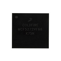
MCF5272VF66 Freescale, MCF5272VF66 Datasheet - Page 222

MCF5272VF66
Manufacturer Part Number
MCF5272VF66
Description
Manufacturer
Freescale
Datasheet
1.MCF5272VF66.pdf
(544 pages)
Specifications of MCF5272VF66
Family Name
MCF5xxx
Device Core
ColdFire
Device Core Size
32b
Frequency (max)
66MHz
Instruction Set Architecture
RISC
Supply Voltage 1 (typ)
3.3V
Operating Temp Range
0C to 70C
Operating Temperature Classification
Commercial
Mounting
Surface Mount
Pin Count
196
Package Type
MA-BGA
Lead Free Status / RoHS Status
Not Compliant
Available stocks
Company
Part Number
Manufacturer
Quantity
Price
Company:
Part Number:
MCF5272VF66
Manufacturer:
HYNIX
Quantity:
19
Company:
Part Number:
MCF5272VF66
Manufacturer:
FREESCAL
Quantity:
885
Company:
Part Number:
MCF5272VF66
Manufacturer:
Freescale Semiconductor
Quantity:
10 000
Part Number:
MCF5272VF66
Manufacturer:
FREESCALE
Quantity:
20 000
Company:
Part Number:
MCF5272VF66J
Manufacturer:
Freescale
Quantity:
256
Company:
Part Number:
MCF5272VF66J
Manufacturer:
Freescale Semiconductor
Quantity:
10 000
Company:
Part Number:
MCF5272VF66R2
Manufacturer:
Freescale Semiconductor
Quantity:
10 000
Company:
Part Number:
MCF5272VF66R2J
Manufacturer:
Freescale Semiconductor
Quantity:
10 000
- Current page: 222 of 544
- Download datasheet (7Mb)
Ethernet Module
The serial mode interface operates in what is generally referred to as AMD mode. The MCF5272
configuration for seven-wire serial mode connections to the external transceiver are shown in
11.4
Figure 11-3
The Ethernet transmitter is designed to work with almost no host intervention. As soon as the driver
enables the FEC transmitter by setting ECR[ETHER_EN] and TDAR[24], the FEC fetches the first
transmit buffer descriptor (TxBD). If the user has a frame ready to transmit, DMA of the transmit data
buffer(s) begins immediately. A collision window (512 bits) of transmit data is sent as a DMA to the
transmit FIFO before off-chip transmission begins.
When the transmit FIFO contains 512 bits of data, the FEC asserts E_TxEN and starts transmitting the
preamble sequence, the start-of-frame delimiter, and then the frame data. However, if the line is busy, the
controller defers the transmission (carrier sense is active). Before transmitting, the controller waits for
carrier sense to become inactive. When carrier sense goes inactive, the controller waits to verify that it
11-4
NOTE: Short Tx frames are padded automatically by the MCF5272
FEC Frame Transmission
Preamble
7 Bytes
shows the Ethernet frame format.
Start Frame
Delimiter
MCF5272 ColdFire
1 Byte
Transmit clock
Transmit enable
Transmit data
Collision
Receive clock
Receive enable
Receive data
Unused, configure as PB14
Unused input, tie to ground
Unused, configure as PB[13:11]
Unused output, ignore
Unused, configure as PB[10:8]
Unused, configure as PB15
Input after reset, connect to ground
Table 11-2. Seven-Wire Mode Configuration
Destination
Address
6 Bytes
Figure 11-3. Ethernet Frame Format
Signal Description
®
Integrated Microprocessor User’s Manual, Rev. 3
Address
6 Bytes
Source
Stored in Transmit Buffer
Stored in Receive Buffer
2 Bytes
Length
Type/
E_TxCLK
E_COL
E_RxCLK
E_CRS
E_RxD[3:1]
E_TxER
E_MDC
E_MDIO
E_TxEN
E_TxD[0]
E_RxDV
E_RxD[0]
E_RxER
E_TxD[3:1]
MCF5272 Pin
46–1500 Bytes
Data
(Pads)
Freescale Semiconductor
Frame Check
Sequence
4 Bytes
Table
11-2.
Related parts for MCF5272VF66
Image
Part Number
Description
Manufacturer
Datasheet
Request
R
Part Number:
Description:
Mcf5272 Coldfire Integrated Microprocessor User
Manufacturer:
Freescale Semiconductor, Inc
Datasheet:

Part Number:
Description:
MCF5272 Interrupt Service Routine for the Physical Layer Interface Controller
Manufacturer:
Freescale Semiconductor / Motorola
Datasheet:

Part Number:
Description:
TOWER ELEVATOR BOARDS HARDWARE
Manufacturer:
Freescale Semiconductor
Datasheet:

Part Number:
Description:
TOWER SERIAL I/O HARDWARE
Manufacturer:
Freescale Semiconductor
Datasheet:

Part Number:
Description:
LCD MODULE FOR TWR SYSTEM
Manufacturer:
Freescale Semiconductor
Datasheet:

Part Number:
Description:
DAUGHTER LCD WVGA I.MX51
Manufacturer:
Freescale Semiconductor
Datasheet:

Part Number:
Description:
TOWER SYSTEM BOARD MPC5125
Manufacturer:
Freescale Semiconductor
Datasheet:

Part Number:
Description:
KIT EVALUATION I.MX51
Manufacturer:
Freescale Semiconductor
Datasheet:

Part Number:
Description:
KIT DEVELOPMENT WINCE IMX25
Manufacturer:
Freescale Semiconductor
Datasheet:

Part Number:
Description:
TOWER SYSTEM KIT MPC5125
Manufacturer:
Freescale Semiconductor
Datasheet:

Part Number:
Description:
TOWER SYSTEM BOARD K40X256
Manufacturer:
Freescale Semiconductor
Datasheet:

Part Number:
Description:
TOWER SYSTEM KIT K40X256
Manufacturer:
Freescale Semiconductor
Datasheet:

Part Number:
Description:
Microcontrollers (MCU) MX28 PLATFORM DEV KIT
Manufacturer:
Freescale Semiconductor
Datasheet:

Part Number:
Description:
MCU, MPU & DSP Development Tools IAR KickStart Kit for Kinetis K60
Manufacturer:
Freescale Semiconductor
Datasheet:

Part Number:
Description:
24BIT HDMI MX535/08
Manufacturer:
Freescale Semiconductor
Datasheet:


