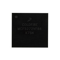
MCF5272VF66 Freescale, MCF5272VF66 Datasheet - Page 379

MCF5272VF66
Manufacturer Part Number
MCF5272VF66
Description
Manufacturer
Freescale
Datasheet
1.MCF5272VF66.pdf
(544 pages)
Specifications of MCF5272VF66
Family Name
MCF5xxx
Device Core
ColdFire
Device Core Size
32b
Frequency (max)
66MHz
Instruction Set Architecture
RISC
Supply Voltage 1 (typ)
3.3V
Operating Temp Range
0C to 70C
Operating Temperature Classification
Commercial
Mounting
Surface Mount
Pin Count
196
Package Type
MA-BGA
Lead Free Status / RoHS Status
Not Compliant
Available stocks
Company
Part Number
Manufacturer
Quantity
Price
Company:
Part Number:
MCF5272VF66
Manufacturer:
HYNIX
Quantity:
19
Company:
Part Number:
MCF5272VF66
Manufacturer:
FREESCAL
Quantity:
885
Company:
Part Number:
MCF5272VF66
Manufacturer:
Freescale Semiconductor
Quantity:
10 000
Part Number:
MCF5272VF66
Manufacturer:
FREESCALE
Quantity:
20 000
Company:
Part Number:
MCF5272VF66J
Manufacturer:
Freescale
Quantity:
256
Company:
Part Number:
MCF5272VF66J
Manufacturer:
Freescale Semiconductor
Quantity:
10 000
Company:
Part Number:
MCF5272VF66R2
Manufacturer:
Freescale Semiconductor
Quantity:
10 000
Company:
Part Number:
MCF5272VF66R2J
Manufacturer:
Freescale Semiconductor
Quantity:
10 000
- Current page: 379 of 544
- Download datasheet (7Mb)
An internal interrupt request signal (IRQ) is provided to notify the interrupt controller of an interrupt
condition. The output is the logical NOR of unmasked UISRn bits. The interrupt levels of the UART
modules are programmed in SIM register ICR2. See
Table 16-15
Figure 16-22
16.5
This section describes operation of the clock source generator, transmitter, and receiver.
16.5.1
CLKIN serves as the basic timing reference for the clock source generator logic, which consists of a clock
generator and a programmable 16+4-bit divider (UDU, UDL, UFPD) dedicated to the UART. The clock
generator cannot produce standard baud rates if CLKIN is used, so the 16-bit divider should be used.
Freescale Semiconductor
Transmitter Serial
Data Output
(URT_TxD)
Receiver Serial Data
Input (URT_RxD)
Clear-to-Send
(URT_CTS)
Request-to-Send
(URT_RTS)
Clock (URT_CLK)
Signal
Operation
Transmitter/Receiver Clock Source
briefly describes the UART module signals.
shows a signal configuration for a UART/RS-232 interface.
The terms ‘assertion’ and ‘negation’ are used to avoid confusion between
active-low and active-high signals. ‘Asserted’ indicates that a signal is
active, independent of the voltage level; ‘negated’ indicates that a signal is
inactive.
URT_TxD is held high (mark condition) when the transmitter is disabled, idle, or operating in the local
loop-back mode. Data is shifted out on URT_TxD on the falling edge of the clock source, with the least
significant bit (lsb) sent first.
Data received on URT_RxD is sampled on the rising edge of the clock source, with the lsb received first.
This input can generate an interrupt on a change of state.
This output can be programmed to be negated or asserted automatically by either the receiver or the
transmitter. It can control serial data flow when connected to a transmitter’s CTS.
The UART’s external clock source. It can be used in 1x or 16x mode. When both the transmitter and
receiver use the timer as the clock source (UCR = 0xDD), the 16x clock is driven out on UARTCLK. If
either the transmitter or receiver use an external clock (1x or 16x), URT_CLK is an input.
MCF5272 ColdFire
URT_CTS
URT_RTS
URT_RxD
URT_TxD
Figure 16-22. UART/RS-232 Interface
UART
Table 16-15. UART Module Signals
®
Integrated Microprocessor User’s Manual, Rev. 3
NOTE
Section 7.2, “Interrupt Controller
Description
RS-232 Transceiver
DI2
DO2
DI1
DO1
Registers.”
UART Modules
16-19
Related parts for MCF5272VF66
Image
Part Number
Description
Manufacturer
Datasheet
Request
R
Part Number:
Description:
Mcf5272 Coldfire Integrated Microprocessor User
Manufacturer:
Freescale Semiconductor, Inc
Datasheet:

Part Number:
Description:
MCF5272 Interrupt Service Routine for the Physical Layer Interface Controller
Manufacturer:
Freescale Semiconductor / Motorola
Datasheet:

Part Number:
Description:
TOWER ELEVATOR BOARDS HARDWARE
Manufacturer:
Freescale Semiconductor
Datasheet:

Part Number:
Description:
TOWER SERIAL I/O HARDWARE
Manufacturer:
Freescale Semiconductor
Datasheet:

Part Number:
Description:
LCD MODULE FOR TWR SYSTEM
Manufacturer:
Freescale Semiconductor
Datasheet:

Part Number:
Description:
DAUGHTER LCD WVGA I.MX51
Manufacturer:
Freescale Semiconductor
Datasheet:

Part Number:
Description:
TOWER SYSTEM BOARD MPC5125
Manufacturer:
Freescale Semiconductor
Datasheet:

Part Number:
Description:
KIT EVALUATION I.MX51
Manufacturer:
Freescale Semiconductor
Datasheet:

Part Number:
Description:
KIT DEVELOPMENT WINCE IMX25
Manufacturer:
Freescale Semiconductor
Datasheet:

Part Number:
Description:
TOWER SYSTEM KIT MPC5125
Manufacturer:
Freescale Semiconductor
Datasheet:

Part Number:
Description:
TOWER SYSTEM BOARD K40X256
Manufacturer:
Freescale Semiconductor
Datasheet:

Part Number:
Description:
TOWER SYSTEM KIT K40X256
Manufacturer:
Freescale Semiconductor
Datasheet:

Part Number:
Description:
Microcontrollers (MCU) MX28 PLATFORM DEV KIT
Manufacturer:
Freescale Semiconductor
Datasheet:

Part Number:
Description:
MCU, MPU & DSP Development Tools IAR KickStart Kit for Kinetis K60
Manufacturer:
Freescale Semiconductor
Datasheet:

Part Number:
Description:
24BIT HDMI MX535/08
Manufacturer:
Freescale Semiconductor
Datasheet:


