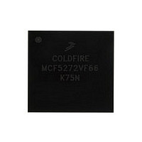
MCF5272VF66 Freescale, MCF5272VF66 Datasheet - Page 388

MCF5272VF66
Manufacturer Part Number
MCF5272VF66
Description
Manufacturer
Freescale
Datasheet
1.MCF5272VF66.pdf
(544 pages)
Specifications of MCF5272VF66
Family Name
MCF5xxx
Device Core
ColdFire
Device Core Size
32b
Frequency (max)
66MHz
Instruction Set Architecture
RISC
Supply Voltage 1 (typ)
3.3V
Operating Temp Range
0C to 70C
Operating Temperature Classification
Commercial
Mounting
Surface Mount
Pin Count
196
Package Type
MA-BGA
Lead Free Status / RoHS Status
Not Compliant
Available stocks
Company
Part Number
Manufacturer
Quantity
Price
Company:
Part Number:
MCF5272VF66
Manufacturer:
HYNIX
Quantity:
19
Company:
Part Number:
MCF5272VF66
Manufacturer:
FREESCAL
Quantity:
885
Company:
Part Number:
MCF5272VF66
Manufacturer:
Freescale Semiconductor
Quantity:
10 000
Part Number:
MCF5272VF66
Manufacturer:
FREESCALE
Quantity:
20 000
Company:
Part Number:
MCF5272VF66J
Manufacturer:
Freescale
Quantity:
256
Company:
Part Number:
MCF5272VF66J
Manufacturer:
Freescale Semiconductor
Quantity:
10 000
Company:
Part Number:
MCF5272VF66R2
Manufacturer:
Freescale Semiconductor
Quantity:
10 000
Company:
Part Number:
MCF5272VF66R2J
Manufacturer:
Freescale Semiconductor
Quantity:
10 000
- Current page: 388 of 544
- Download datasheet (7Mb)
UART Modules
Because the receiver is not active, received data cannot be read by the CPU and error status conditions are
inactive. Received parity is not checked and is not recalculated for transmission. Stop bits are sent as they
are received. A received break is echoed as received until the next valid start bit is detected.
16.5.4
Setting UMR1n[PM] programs the UART to operate in a wake-up mode for multidrop or multiprocessor
applications. In this mode, a master can transmit an address character followed by a block of data
characters targeted for one of up to 256 slave stations.
Although slave stations have their channel receivers disabled, they continuously monitor the master’s data
stream. When the master sends an address character, the slave receiver channel notifies its respective CPU
by setting USRn[RxRDY] and generating an interrupt (if programmed to do so). Each slave station CPU
then compares the received address to its station address and enables its receiver if it wishes to receive the
subsequent data characters or block of data from the master station. Slave stations not addressed continue
monitoring the data stream. Data fields in the data stream are separated by an address character. After a
slave receives a block of data, its CPU disables the receiver and repeats the process.Functional timing
information for multidrop mode is shown in
A character sent from the master station consists of a start bit, a programmed number of data bits, an
address/data (A/D) bit flag, and a programmed number of stop bits. A/D = 1 indicates an address character;
A/D = 0 indicates a data character. The polarity of A/D is selected through UMR1n[PT]. UMR1n should
be programmed before enabling the transmitter and loading the corresponding data bits into the transmit
buffer.
In multidrop mode, the receiver continuously monitors the received data stream, regardless of whether it
is enabled or disabled. If the receiver is disabled, it sets the RxRDY bit and loads the character into the
receiver holding register FIFO stack provided the received A/D bit is a one (address tag). The character is
discarded if the received A/D bit is zero (data tag). If the receiver is enabled, all received characters are
transferred to the CPU through the receiver holding register stack during read operations.
In either case, the data bits are loaded into the data portion of the stack while the A/D bit is loaded into the
status portion of the stack normally used for a parity error (USRn[PE]).
Detection of breaks and framing or overrun errors operates normally. The A/D bit replaces the parity bit,
so parity is neither calculated nor checked. Messages in this mode may still contain error detection and
correction information. If 8-bit characters are not required, software can be used to calculate parity and
append it to the 5-, 6-, or 7-bit character.
16-28
Multidrop Mode
MCF5272 ColdFire
CPU
Disabled
Disabled
Figure 16-29. Remote Loop-Back
®
Integrated Microprocessor User’s Manual, Rev. 3
Figure
Rx
Tx
16-30.
Disabled
Disabled
RxD Input
TxD Input
Freescale Semiconductor
Related parts for MCF5272VF66
Image
Part Number
Description
Manufacturer
Datasheet
Request
R
Part Number:
Description:
Mcf5272 Coldfire Integrated Microprocessor User
Manufacturer:
Freescale Semiconductor, Inc
Datasheet:

Part Number:
Description:
MCF5272 Interrupt Service Routine for the Physical Layer Interface Controller
Manufacturer:
Freescale Semiconductor / Motorola
Datasheet:

Part Number:
Description:
TOWER ELEVATOR BOARDS HARDWARE
Manufacturer:
Freescale Semiconductor
Datasheet:

Part Number:
Description:
TOWER SERIAL I/O HARDWARE
Manufacturer:
Freescale Semiconductor
Datasheet:

Part Number:
Description:
LCD MODULE FOR TWR SYSTEM
Manufacturer:
Freescale Semiconductor
Datasheet:

Part Number:
Description:
DAUGHTER LCD WVGA I.MX51
Manufacturer:
Freescale Semiconductor
Datasheet:

Part Number:
Description:
TOWER SYSTEM BOARD MPC5125
Manufacturer:
Freescale Semiconductor
Datasheet:

Part Number:
Description:
KIT EVALUATION I.MX51
Manufacturer:
Freescale Semiconductor
Datasheet:

Part Number:
Description:
KIT DEVELOPMENT WINCE IMX25
Manufacturer:
Freescale Semiconductor
Datasheet:

Part Number:
Description:
TOWER SYSTEM KIT MPC5125
Manufacturer:
Freescale Semiconductor
Datasheet:

Part Number:
Description:
TOWER SYSTEM BOARD K40X256
Manufacturer:
Freescale Semiconductor
Datasheet:

Part Number:
Description:
TOWER SYSTEM KIT K40X256
Manufacturer:
Freescale Semiconductor
Datasheet:

Part Number:
Description:
Microcontrollers (MCU) MX28 PLATFORM DEV KIT
Manufacturer:
Freescale Semiconductor
Datasheet:

Part Number:
Description:
MCU, MPU & DSP Development Tools IAR KickStart Kit for Kinetis K60
Manufacturer:
Freescale Semiconductor
Datasheet:

Part Number:
Description:
24BIT HDMI MX535/08
Manufacturer:
Freescale Semiconductor
Datasheet:


