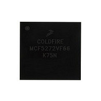
MCF5272VF66 Freescale, MCF5272VF66 Datasheet - Page 21

MCF5272VF66
Manufacturer Part Number
MCF5272VF66
Description
Manufacturer
Freescale
Datasheet
1.MCF5272VF66.pdf
(544 pages)
Specifications of MCF5272VF66
Family Name
MCF5xxx
Device Core
ColdFire
Device Core Size
32b
Frequency (max)
66MHz
Instruction Set Architecture
RISC
Supply Voltage 1 (typ)
3.3V
Operating Temp Range
0C to 70C
Operating Temperature Classification
Commercial
Mounting
Surface Mount
Pin Count
196
Package Type
MA-BGA
Lead Free Status / RoHS Status
Not Compliant
Available stocks
Company
Part Number
Manufacturer
Quantity
Price
Company:
Part Number:
MCF5272VF66
Manufacturer:
HYNIX
Quantity:
19
Company:
Part Number:
MCF5272VF66
Manufacturer:
FREESCAL
Quantity:
885
Company:
Part Number:
MCF5272VF66
Manufacturer:
Freescale Semiconductor
Quantity:
10 000
Part Number:
MCF5272VF66
Manufacturer:
FREESCALE
Quantity:
20 000
Company:
Part Number:
MCF5272VF66J
Manufacturer:
Freescale
Quantity:
256
Company:
Part Number:
MCF5272VF66J
Manufacturer:
Freescale Semiconductor
Quantity:
10 000
Company:
Part Number:
MCF5272VF66R2
Manufacturer:
Freescale Semiconductor
Quantity:
10 000
Company:
Part Number:
MCF5272VF66R2J
Manufacturer:
Freescale Semiconductor
Quantity:
10 000
- Current page: 21 of 544
- Download datasheet (7Mb)
Paragraph
Number
12.4 Software Architecture and Application Notes ......................................................................... 12-31
12.5 Line Interface ........................................................................................................................... 12-36
13.1 Introduction ................................................................................................................................ 13-1
13.2 GCI/IDL Block .......................................................................................................................... 13-3
13.3 PLIC Timing Generator ........................................................................................................... 13-11
Freescale Semiconductor
12.4.1 USB Module Initialization ........................................................................................... 12-31
12.4.2 USB Configuration and Interface Changes .................................................................. 12-31
12.4.3 FIFO Configuration ...................................................................................................... 12-32
12.4.4 Data Flow ..................................................................................................................... 12-32
12.4.5 Class- and Vendor-Specific Request Operation ............................................................ 12-34
12.4.6 remote wakeup and resume Operation ......................................................................... 12-35
12.4.7 Endpoint Halt Feature ................................................................................................... 12-35
12.5.1 Attachment Detection ................................................................................................... 12-36
12.5.2 PCB Layout Recommendations ................................................................................... 12-36
12.5.3 Recommended USB Protection Circuit ........................................................................ 12-37
13.2.1 GCI/IDL B- and D-Channel Receive Data Registers ..................................................... 13-3
13.2.2 GCI/IDL B- and D-Channel Transmit Data Registers ................................................... 13-4
13.2.3 GCI/IDL B- and D-Channel Bit Alignment ................................................................... 13-5
13.2.4 GCI/IDL Looping Modes ............................................................................................... 13-8
13.2.5 GCI/IDL Interrupts ......................................................................................................... 13-9
12.4.4.1 Control, Bulk, and Interrupt Endpoints .......................................................... 12-33
12.4.4.2 Isochronous Endpoints .................................................................................... 12-33
13.2.3.1 B-Channel Unencoded Data ............................................................................. 13-5
13.2.3.2 B-Channel HDLC Encoded Data ...................................................................... 13-6
13.2.3.3 D-Channel HDLC Encoded Data ..................................................................... 13-6
13.2.3.4 D-Channel Unencoded Data ............................................................................. 13-7
13.2.3.5
13.2.4.1 Automatic Echo Mode ...................................................................................... 13-9
13.2.4.2 Local Loopback Mode ...................................................................................... 13-9
13.2.4.3 Remote Loopback Mode ................................................................................... 13-9
13.2.5.1 GCI/IDL Periodic Frame Interrupt ................................................................... 13-9
13.2.5.2
13.2.5.3 Interrupt Control ............................................................................................. 13-11
12.4.4.1.1 IN Endpoints .......................................................................................... 12-33
12.4.4.1.2 OUT Endpoints ...................................................................................... 12-33
12.4.4.2.1 IN Endpoints .......................................................................................... 12-34
12.4.4.2.2 OUT Endpoints ...................................................................................... 12-34
MCF5272 ColdFire
GCI/IDL D-Channel Contention ..................................................................... 13-8
GCI Aperiodic Status Interrupt ...................................................................... 13-10
Physical Layer Interface Controller (PLIC)
Table of Contents (Continued)
®
Integrated Microprocessor User’s Manual, Rev. 3
Chapter 13
Title
Number
Page
xxi
Related parts for MCF5272VF66
Image
Part Number
Description
Manufacturer
Datasheet
Request
R
Part Number:
Description:
Mcf5272 Coldfire Integrated Microprocessor User
Manufacturer:
Freescale Semiconductor, Inc
Datasheet:

Part Number:
Description:
MCF5272 Interrupt Service Routine for the Physical Layer Interface Controller
Manufacturer:
Freescale Semiconductor / Motorola
Datasheet:

Part Number:
Description:
TOWER ELEVATOR BOARDS HARDWARE
Manufacturer:
Freescale Semiconductor
Datasheet:

Part Number:
Description:
TOWER SERIAL I/O HARDWARE
Manufacturer:
Freescale Semiconductor
Datasheet:

Part Number:
Description:
LCD MODULE FOR TWR SYSTEM
Manufacturer:
Freescale Semiconductor
Datasheet:

Part Number:
Description:
DAUGHTER LCD WVGA I.MX51
Manufacturer:
Freescale Semiconductor
Datasheet:

Part Number:
Description:
TOWER SYSTEM BOARD MPC5125
Manufacturer:
Freescale Semiconductor
Datasheet:

Part Number:
Description:
KIT EVALUATION I.MX51
Manufacturer:
Freescale Semiconductor
Datasheet:

Part Number:
Description:
KIT DEVELOPMENT WINCE IMX25
Manufacturer:
Freescale Semiconductor
Datasheet:

Part Number:
Description:
TOWER SYSTEM KIT MPC5125
Manufacturer:
Freescale Semiconductor
Datasheet:

Part Number:
Description:
TOWER SYSTEM BOARD K40X256
Manufacturer:
Freescale Semiconductor
Datasheet:

Part Number:
Description:
TOWER SYSTEM KIT K40X256
Manufacturer:
Freescale Semiconductor
Datasheet:

Part Number:
Description:
Microcontrollers (MCU) MX28 PLATFORM DEV KIT
Manufacturer:
Freescale Semiconductor
Datasheet:

Part Number:
Description:
MCU, MPU & DSP Development Tools IAR KickStart Kit for Kinetis K60
Manufacturer:
Freescale Semiconductor
Datasheet:

Part Number:
Description:
24BIT HDMI MX535/08
Manufacturer:
Freescale Semiconductor
Datasheet:


