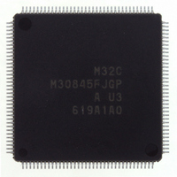
M30845FJGP#U3 Renesas Electronics America, M30845FJGP#U3 Datasheet - Page 504

M30845FJGP#U3
Manufacturer Part Number
M30845FJGP#U3
Description
IC M32C MCU FLASH 512K 144LQFP
Manufacturer
Renesas Electronics America
Series
M16C™ M32C/80r
Specifications of M30845FJGP#U3
Core Processor
M32C/80
Core Size
16/32-Bit
Speed
32MHz
Connectivity
CAN, I²C, IEBus, SIO, UART/USART
Peripherals
DMA, PWM, WDT
Number Of I /o
121
Program Memory Size
512KB (512K x 8)
Program Memory Type
FLASH
Ram Size
24K x 8
Voltage - Supply (vcc/vdd)
3 V ~ 5.5 V
Data Converters
A/D 34x10b, D/A 2x8b
Oscillator Type
Internal
Operating Temperature
-40°C ~ 85°C
Package / Case
144-LQFP
Lead Free Status / RoHS Status
Lead free / RoHS Compliant
Eeprom Size
-
Available stocks
Company
Part Number
Manufacturer
Quantity
Price
- Current page: 504 of 531
- Download datasheet (4Mb)
M
R
R
e
E
3
. v
J
2
0
C
1
9
8 /
0 .
B
0
1
4
27.9.2.3 Timer A (One-shot Timer Mode)
27.9.2.4 Timer A (Pulse Width Modulation Mode)
0
G
• The IR bit is set to "1" when the following procedures are performed to set timer mode:
3
J
6
• The TAiS (i=0 to 4) bit in the TABSR register is set to "0" (stops counting) after reset. Set the TAiS
• The followings occur when the TABSR register is set to "0" (stops counting) while counting:
• The output of the one-shot timer is synchronized with an internal count source. When set to an
• When a trigger is generated while counting, the reload register reloads and continues counting
• If an external trigger input is selected to start counting in timer A one-shot timer mode, do not
• The TAiS(i=0 to 4) bit in the TABSR register is set to "0" (stops counting) after reset. Set the TAiS bit
• The IR bit is set to "1" when the following procedures are performed to set timer mode:
• The followings occur when the TAiS bit is set to "0" (stops counting) while PWM pulse is output:
u
o r
Therefore, set the IR bit to "0" to generate a timer Ai interrupt (IR bit) after performing these proce-
0 -
. l
bit to "1" (starts counting) after selecting an operating mode and setting the TAi register.
- The counter stops counting and the microcomputer reloads contents of the reload register.
- The TAi
- The IR bit in the TAiIC register is set to "1" (interrupt requested) after one CPU clock cycle.
external trigger, there is a delay of one count source cycle maximum, from trigger input to the TAi
pin to the one-shot timer output.
- selecting one-shot timer mode after reset.
- switching from timer mode to one-shot timer mode.
- switching from event counter mode to one-shot timer mode.
dures.
after the counter has decremented once following a re-trigger. To generate a trigger while counting,
wait at least 1 count source cycle after the previous trigger has been generated and generate a re-
trigger.
provide another external trigger input again for 300 ns before the timer A counter value reaches
"0000
to "1" (starts counting) after selecting an operating mode and setting the TAi register.
- Selecting PWM mode after reset
- Switching from timer mode to PWM mode
- Switching from event counter mode to PWM mode
Therefore, set the IR bit to "0" by program to generate a timer Ai interrupt (IR bit) after performing
these procedures.
- The counter stops counting
- Output level changes to low ("L") and the IR bit changes to "1" when the TAi
- The IR bit and the output level remain unchanged when TAi
u
0
1
p
, 7
0
1
(
2
M
16
0
3
0
". One-shot timer may stop counting.
2
5
OUT
C
8 /
Page 481
, 4
pin becomes low ("L").
M
3
2
C
8 /
f o
4
4
) T
9
5
OUT
pin is held "L"
OUT
27. Precautions (Timer)
pin is held high ("H")
IN
Related parts for M30845FJGP#U3
Image
Part Number
Description
Manufacturer
Datasheet
Request
R

Part Number:
Description:
KIT STARTER FOR M16C/29
Manufacturer:
Renesas Electronics America
Datasheet:

Part Number:
Description:
KIT STARTER FOR R8C/2D
Manufacturer:
Renesas Electronics America
Datasheet:

Part Number:
Description:
R0K33062P STARTER KIT
Manufacturer:
Renesas Electronics America
Datasheet:

Part Number:
Description:
KIT STARTER FOR R8C/23 E8A
Manufacturer:
Renesas Electronics America
Datasheet:

Part Number:
Description:
KIT STARTER FOR R8C/25
Manufacturer:
Renesas Electronics America
Datasheet:

Part Number:
Description:
KIT STARTER H8S2456 SHARPE DSPLY
Manufacturer:
Renesas Electronics America
Datasheet:

Part Number:
Description:
KIT STARTER FOR R8C38C
Manufacturer:
Renesas Electronics America
Datasheet:

Part Number:
Description:
KIT STARTER FOR R8C35C
Manufacturer:
Renesas Electronics America
Datasheet:

Part Number:
Description:
KIT STARTER FOR R8CL3AC+LCD APPS
Manufacturer:
Renesas Electronics America
Datasheet:

Part Number:
Description:
KIT STARTER FOR RX610
Manufacturer:
Renesas Electronics America
Datasheet:

Part Number:
Description:
KIT STARTER FOR R32C/118
Manufacturer:
Renesas Electronics America
Datasheet:

Part Number:
Description:
KIT DEV RSK-R8C/26-29
Manufacturer:
Renesas Electronics America
Datasheet:

Part Number:
Description:
KIT STARTER FOR SH7124
Manufacturer:
Renesas Electronics America
Datasheet:

Part Number:
Description:
KIT STARTER FOR H8SX/1622
Manufacturer:
Renesas Electronics America
Datasheet:

Part Number:
Description:
KIT DEV FOR SH7203
Manufacturer:
Renesas Electronics America
Datasheet:


