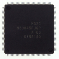
M30845FJGP#U3 Renesas Electronics America, M30845FJGP#U3 Datasheet - Page 10

M30845FJGP#U3
Manufacturer Part Number
M30845FJGP#U3
Description
IC M32C MCU FLASH 512K 144LQFP
Manufacturer
Renesas Electronics America
Series
M16C™ M32C/80r
Specifications of M30845FJGP#U3
Core Processor
M32C/80
Core Size
16/32-Bit
Speed
32MHz
Connectivity
CAN, I²C, IEBus, SIO, UART/USART
Peripherals
DMA, PWM, WDT
Number Of I /o
121
Program Memory Size
512KB (512K x 8)
Program Memory Type
FLASH
Ram Size
24K x 8
Voltage - Supply (vcc/vdd)
3 V ~ 5.5 V
Data Converters
A/D 34x10b, D/A 2x8b
Oscillator Type
Internal
Operating Temperature
-40°C ~ 85°C
Package / Case
144-LQFP
Lead Free Status / RoHS Status
Lead free / RoHS Compliant
Eeprom Size
-
Available stocks
Company
Part Number
Manufacturer
Quantity
Price
- Current page: 10 of 531
- Download datasheet (4Mb)
16. Three-Phase Motor Control Timer Functions ____ 182
17. Serial I/O __________________________________ 193
18. A/D Converter ______________________________ 246
17.1 Clock Synchronous Serial I/O Mode .................................................................. 203
17.2 Clock Asynchronous Serial I/O (UART) Mode ................................................... 209
17.3 Special Mode 1 (I
17.4 Special Mode 2 ..................................................................................................... 226
17.5 Special Mode 3 (GCI Mode) ................................................................................. 232
17.6 Special Mode 4 (IE Mode) .................................................................................... 236
17.7 Special Mode 5 (SIM Mode) ................................................................................. 240
18.1 Mode Description ................................................................................................. 254
17.1.1 Selecting CLK Polarity Selecting ................................................................ 207
17.1.2 Selecting LSB First or MSB First ................................................................. 207
17.1.3 Continuous Receive Mode ........................................................................... 208
17.1.4 Serial Data Logic Inverse ............................................................................. 208
17.2.1 Transfer Speed .............................................................................................. 213
17.2.2 Selecting LSB First or MSB First ................................................................. 214
17.2.3 Serial Data Logic Inverse ............................................................................. 214
17.2.4 TxD and RxD I/O Polarity Inverse ................................................................ 215
17.3.1 Detecting Start Condition and Stop Condition .......................................... 222
17.3.2 Start Condition or Stop Condition Output .................................................. 222
17.3.3 Arbitration ...................................................................................................... 224
17.3.4 Transfer Clock ............................................................................................... 224
17.3.5 SDA Output .................................................................................................... 224
17.3.6 SDA Input ....................................................................................................... 225
17.3.7 ACK, NACK .................................................................................................... 225
17.3.8 Transmit and Receive Reset ........................................................................ 225
17.4.1 SSi Input Pin Function (i=0 to 4) .................................................................. 229
17.4.2 Clock Phase Setting Function ..................................................................... 230
17.7.1 Parity Error Signal ........................................................................................ 244
17.7.2 Format ............................................................................................................ 245
18.1.1 One-shot Mode .............................................................................................. 254
18.1.2 Repeat Mode .................................................................................................. 255
18.1.3 Single Sweep Mode ...................................................................................... 256
18.1.4 Repeat Sweep Mode 0 .................................................................................. 257
18.1.5 Repeat Sweep Mode 1 .................................................................................. 258
18.1.6 Multi-Port Single Sweep Mode ..................................................................... 259
18.1.7 Multi-Port Repeat Sweep Mode 0 ................................................................ 260
______
2
C Mode) .................................................................................. 216
A-5
Related parts for M30845FJGP#U3
Image
Part Number
Description
Manufacturer
Datasheet
Request
R

Part Number:
Description:
KIT STARTER FOR M16C/29
Manufacturer:
Renesas Electronics America
Datasheet:

Part Number:
Description:
KIT STARTER FOR R8C/2D
Manufacturer:
Renesas Electronics America
Datasheet:

Part Number:
Description:
R0K33062P STARTER KIT
Manufacturer:
Renesas Electronics America
Datasheet:

Part Number:
Description:
KIT STARTER FOR R8C/23 E8A
Manufacturer:
Renesas Electronics America
Datasheet:

Part Number:
Description:
KIT STARTER FOR R8C/25
Manufacturer:
Renesas Electronics America
Datasheet:

Part Number:
Description:
KIT STARTER H8S2456 SHARPE DSPLY
Manufacturer:
Renesas Electronics America
Datasheet:

Part Number:
Description:
KIT STARTER FOR R8C38C
Manufacturer:
Renesas Electronics America
Datasheet:

Part Number:
Description:
KIT STARTER FOR R8C35C
Manufacturer:
Renesas Electronics America
Datasheet:

Part Number:
Description:
KIT STARTER FOR R8CL3AC+LCD APPS
Manufacturer:
Renesas Electronics America
Datasheet:

Part Number:
Description:
KIT STARTER FOR RX610
Manufacturer:
Renesas Electronics America
Datasheet:

Part Number:
Description:
KIT STARTER FOR R32C/118
Manufacturer:
Renesas Electronics America
Datasheet:

Part Number:
Description:
KIT DEV RSK-R8C/26-29
Manufacturer:
Renesas Electronics America
Datasheet:

Part Number:
Description:
KIT STARTER FOR SH7124
Manufacturer:
Renesas Electronics America
Datasheet:

Part Number:
Description:
KIT STARTER FOR H8SX/1622
Manufacturer:
Renesas Electronics America
Datasheet:

Part Number:
Description:
KIT DEV FOR SH7203
Manufacturer:
Renesas Electronics America
Datasheet:


