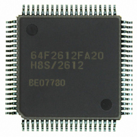
HD64F2612FA20 Renesas Electronics America, HD64F2612FA20 Datasheet - Page 30

HD64F2612FA20
Manufacturer Part Number
HD64F2612FA20
Description
IC H8S MCU FLASH 128K 80QFP
Manufacturer
Renesas Electronics America
Series
H8® H8S/2600r
Specifications of HD64F2612FA20
Core Processor
H8S/2600
Core Size
16-Bit
Speed
20MHz
Connectivity
CAN, SCI
Peripherals
POR, PWM, WDT
Number Of I /o
43
Program Memory Size
128KB (128K x 8)
Program Memory Type
FLASH
Ram Size
4K x 8
Voltage - Supply (vcc/vdd)
4.5 V ~ 5.5 V
Data Converters
A/D 12x10b
Oscillator Type
Internal
Operating Temperature
-20°C ~ 75°C
Package / Case
80-QFP
Lead Free Status / RoHS Status
Contains lead / RoHS non-compliant
Eeprom Size
-
Available stocks
Company
Part Number
Manufacturer
Quantity
Price
Part Number:
HD64F2612FA20
Manufacturer:
RENESAS/瑞萨
Quantity:
20 000
Part Number:
HD64F2612FA20J
Manufacturer:
RENESAS/瑞萨
Quantity:
20 000
- Current page: 30 of 606
- Download datasheet (4Mb)
Figure 18.6
Figure 18.7
Figure 18.8
Figure 18.9
Figure 18.10 Erase/Erase-Verify Flowchart ................................................................................ 473
Section 19 Clock Pulse Generator
Figure 19.1
Figure 19.2
Figure 19.3
Figure 19.4
Figure 19.5
Figure 19.6
Figure 19.7
Section 20 Power-Down Modes
Figure 20.1
Figure 20.2
Figure 20.3
Figure 20.4
Figure 20.5
Section 21 Electrical Characteristics
Figure 21.1
Figure 21.2
Figure 21.3
Figure 21.4
Figure 21.5
Figure 21.6
Figure 21.7
Figure 21.8
Figure 21.9
Figure 21.10 SCI Input/Output Timing (Clock Synchronous Mode) .......................................... 514
Figure 21.11 A/D Converter External Trigger Input Timing....................................................... 514
Figure 21.12 HCAN Input/Output Timing .................................................................................. 514
Figure 21.13 PPG Output Timing................................................................................................ 514
Figure 21.14 MMT Input/Output Timing .................................................................................... 515
Figure 21.15 POE Input/Output Timing ...................................................................................... 515
Appendix
Figure D.1
Rev. 7.00 Sep. 11, 2009 Page xxviii of xxxiv
REJ09B0211-0700
Programming/Erasing Flowchart Example in User Program Mode....................... 467
Flowchart for Flash Memory Emulation in RAM .................................................. 468
Example of RAM Overlap Operation..................................................................... 469
Program/Program-Verify Flowchart ...................................................................... 471
Block Diagram of Clock Pulse Generator .............................................................. 477
Connection of Crystal Resonator (Example).......................................................... 480
Crystal Resonator Equivalent Circuit..................................................................... 480
External Clock Input (Examples) ........................................................................... 481
External Clock Input Timing.................................................................................. 482
Note on Board Design of Oscillator Circuit ........................................................... 484
External Circuitry Recommended for PLL Circuit ................................................ 485
Mode Transition Diagram ...................................................................................... 488
Medium-Speed Mode Transition and Clearance Timing ....................................... 494
Software Standby Mode Application Example ...................................................... 498
Timing of Transition to Hardware Standby Mode ................................................. 499
Timing of Recovery from Hardware Standby Mode.............................................. 500
Output Load Circuit ............................................................................................... 507
System Clock Timing............................................................................................. 508
Oscillation Stabilization Timing ............................................................................ 509
Reset Input Timing................................................................................................. 510
Interrupt Input Timing............................................................................................ 510
I/O Port Input/Output Timing................................................................................. 512
TPU Input/Output Timing ...................................................................................... 513
TPU Clock Input Timing........................................................................................ 513
SCK Clock Input Timing ....................................................................................... 513
FP-80Q, FP-80QV Package Dimensions ............................................................... 561
Related parts for HD64F2612FA20
Image
Part Number
Description
Manufacturer
Datasheet
Request
R

Part Number:
Description:
KIT STARTER FOR M16C/29
Manufacturer:
Renesas Electronics America
Datasheet:

Part Number:
Description:
KIT STARTER FOR R8C/2D
Manufacturer:
Renesas Electronics America
Datasheet:

Part Number:
Description:
R0K33062P STARTER KIT
Manufacturer:
Renesas Electronics America
Datasheet:

Part Number:
Description:
KIT STARTER FOR R8C/23 E8A
Manufacturer:
Renesas Electronics America
Datasheet:

Part Number:
Description:
KIT STARTER FOR R8C/25
Manufacturer:
Renesas Electronics America
Datasheet:

Part Number:
Description:
KIT STARTER H8S2456 SHARPE DSPLY
Manufacturer:
Renesas Electronics America
Datasheet:

Part Number:
Description:
KIT STARTER FOR R8C38C
Manufacturer:
Renesas Electronics America
Datasheet:

Part Number:
Description:
KIT STARTER FOR R8C35C
Manufacturer:
Renesas Electronics America
Datasheet:

Part Number:
Description:
KIT STARTER FOR R8CL3AC+LCD APPS
Manufacturer:
Renesas Electronics America
Datasheet:

Part Number:
Description:
KIT STARTER FOR RX610
Manufacturer:
Renesas Electronics America
Datasheet:

Part Number:
Description:
KIT STARTER FOR R32C/118
Manufacturer:
Renesas Electronics America
Datasheet:

Part Number:
Description:
KIT DEV RSK-R8C/26-29
Manufacturer:
Renesas Electronics America
Datasheet:

Part Number:
Description:
KIT STARTER FOR SH7124
Manufacturer:
Renesas Electronics America
Datasheet:

Part Number:
Description:
KIT STARTER FOR H8SX/1622
Manufacturer:
Renesas Electronics America
Datasheet:


