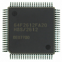
HD64F2612FA20 Renesas Electronics America, HD64F2612FA20 Datasheet - Page 23

HD64F2612FA20
Manufacturer Part Number
HD64F2612FA20
Description
IC H8S MCU FLASH 128K 80QFP
Manufacturer
Renesas Electronics America
Series
H8® H8S/2600r
Specifications of HD64F2612FA20
Core Processor
H8S/2600
Core Size
16-Bit
Speed
20MHz
Connectivity
CAN, SCI
Peripherals
POR, PWM, WDT
Number Of I /o
43
Program Memory Size
128KB (128K x 8)
Program Memory Type
FLASH
Ram Size
4K x 8
Voltage - Supply (vcc/vdd)
4.5 V ~ 5.5 V
Data Converters
A/D 12x10b
Oscillator Type
Internal
Operating Temperature
-20°C ~ 75°C
Package / Case
80-QFP
Lead Free Status / RoHS Status
Contains lead / RoHS non-compliant
Eeprom Size
-
Available stocks
Company
Part Number
Manufacturer
Quantity
Price
Part Number:
HD64F2612FA20
Manufacturer:
RENESAS/瑞萨
Quantity:
20 000
Part Number:
HD64F2612FA20J
Manufacturer:
RENESAS/瑞萨
Quantity:
20 000
- Current page: 23 of 606
- Download datasheet (4Mb)
20.4 Software Standby Mode..................................................................................................... 496
20.5 Hardware Standby Mode ................................................................................................... 499
20.6 Module Stop Mode............................................................................................................. 500
20.7 φ Clock Output Disabling Function ................................................................................... 501
20.8 Usage Notes ....................................................................................................................... 502
Section 21 Electrical Characteristics .................................................................503
21.1 Absolute Maximum Ratings .............................................................................................. 503
21.2 DC Characteristics ............................................................................................................. 504
21.3 AC Characteristics ............................................................................................................. 507
21.4 A/D Conversion Characteristics......................................................................................... 516
21.5 Flash Memory Characteristics............................................................................................ 517
Appendix
A.
B.
C.
D.
Index
20.3.2 Clearing Sleep Mode............................................................................................. 495
20.4.1 Transition to Software Standby Mode .................................................................. 496
20.4.2 Clearing Software Standby Mode ......................................................................... 496
20.4.3 Setting Oscillation Stabilization Time after Clearing Software Standby Mode.... 497
20.4.4 Software Standby Mode Application Example..................................................... 498
20.5.1 Transition to Hardware Standby Mode ................................................................. 499
20.5.2 Clearing Hardware Standby Mode........................................................................ 499
20.5.3 Hardware Standby Mode Timings ........................................................................ 499
20.8.1 I/O Port Status....................................................................................................... 502
20.8.2 Current Dissipation during Oscillation Stabilization Wait Period ........................ 502
20.8.3 DTC Module Stop................................................................................................. 502
20.8.4 On-Chip Supporting Module Interrupt.................................................................. 502
20.8.5 Writing to MSTPCR ............................................................................................. 502
21.3.1 Clock Timing ........................................................................................................ 508
21.3.2 Control Signal Timing .......................................................................................... 509
21.3.3 Timing of On-Chip Supporting Modules.............................................................. 511
On-Chip I/O Register ......................................................................................................... 519
A.1
A.2
A.3
I/O Port States in Each Pin State........................................................................................ 559
Product Code Lineup ......................................................................................................... 560
Package Dimensions .......................................................................................................... 561
..........................................................................................................519
Register Addresses................................................................................................ 519
Register Bits.......................................................................................................... 534
Register States in Each Operating Mode .............................................................. 548
..........................................................................................................563
Rev. 7.00 Sep. 11, 2009 Page xxi of xxxiv
REJ09B0211-0700
Related parts for HD64F2612FA20
Image
Part Number
Description
Manufacturer
Datasheet
Request
R

Part Number:
Description:
KIT STARTER FOR M16C/29
Manufacturer:
Renesas Electronics America
Datasheet:

Part Number:
Description:
KIT STARTER FOR R8C/2D
Manufacturer:
Renesas Electronics America
Datasheet:

Part Number:
Description:
R0K33062P STARTER KIT
Manufacturer:
Renesas Electronics America
Datasheet:

Part Number:
Description:
KIT STARTER FOR R8C/23 E8A
Manufacturer:
Renesas Electronics America
Datasheet:

Part Number:
Description:
KIT STARTER FOR R8C/25
Manufacturer:
Renesas Electronics America
Datasheet:

Part Number:
Description:
KIT STARTER H8S2456 SHARPE DSPLY
Manufacturer:
Renesas Electronics America
Datasheet:

Part Number:
Description:
KIT STARTER FOR R8C38C
Manufacturer:
Renesas Electronics America
Datasheet:

Part Number:
Description:
KIT STARTER FOR R8C35C
Manufacturer:
Renesas Electronics America
Datasheet:

Part Number:
Description:
KIT STARTER FOR R8CL3AC+LCD APPS
Manufacturer:
Renesas Electronics America
Datasheet:

Part Number:
Description:
KIT STARTER FOR RX610
Manufacturer:
Renesas Electronics America
Datasheet:

Part Number:
Description:
KIT STARTER FOR R32C/118
Manufacturer:
Renesas Electronics America
Datasheet:

Part Number:
Description:
KIT DEV RSK-R8C/26-29
Manufacturer:
Renesas Electronics America
Datasheet:

Part Number:
Description:
KIT STARTER FOR SH7124
Manufacturer:
Renesas Electronics America
Datasheet:

Part Number:
Description:
KIT STARTER FOR H8SX/1622
Manufacturer:
Renesas Electronics America
Datasheet:


