DK-DEV-4SGX230N Altera, DK-DEV-4SGX230N Datasheet - Page 973
DK-DEV-4SGX230N
Manufacturer Part Number
DK-DEV-4SGX230N
Description
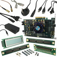
KIT DEVELOPMENT STRATIX IV
Manufacturer
Altera
Series
Stratix® IVr
Type
FPGAr
Datasheets
1.EP4SGX110DF29C3N.pdf
(80 pages)
2.EP4SGX110DF29C3N.pdf
(1154 pages)
3.DK-DEV-4SGX230N.pdf
(2 pages)
4.DK-DEV-4SGX530N.pdf
(57 pages)
Specifications of DK-DEV-4SGX230N
Contents
Development Board, Universal Power Supply, Cables and Software
Silicon Manufacturer
Altera
Core Architecture
FPGA
Core Sub-architecture
Stratix
Silicon Core Number
EP4S
Silicon Family Name
Stratix IV GX
Rohs Compliant
Yes
For Use With/related Products
EP4SGX230K
Lead Free Status / RoHS Status
Lead free / RoHS Compliant
Other names
544-2594
Available stocks
Company
Part Number
Manufacturer
Quantity
Price
Company:

Part Number:
DK-DEV-4SGX230N
Manufacturer:
Altera
Quantity:
135


Chapter 1: ALTGX Transceiver Setup Guide for Stratix IV Devices
Parameter Settings
Table 1–2. MegaWizard Plug-In Manager Options (PLL/Ports Screen) (Part 2 of 3)
February 2011 Altera Corporation
Enable PLL phase frequency
detector (PFD) feedback to
compensate latency
uncertainty in tx_dataout
and tx_clkout paths
relative to the reference
clock.
What is the TX PLL
bandwidth mode?
What is the receiver CDR
bandwidth mode?
What is the acceptable PPM
threshold between the
receiver CDR VCO and the
receiver input reference
clock?
Optional Ports
Create a gxb_powerdown
port to power down the
transceiver block.
Create a pll_powerdown
port to power down the TX
PLL.
Create a rx_analogreset
port for the analog portion of
the receiver.
ALTGX Setting
This option applies only when you select
Deterministic Latency functional mode.
The available options are Auto, Low, Medium, and
High. Select the appropriate option based on your
system requirements.
The available options are Auto, Low, Medium, and
High. Select the appropriate option based on your
system requirements.
In Automatic Lock mode, the CDR remains in
Lock-to-Data (LTD) mode as long as the parts per
million (PPM) difference between the CDR VCO
output clock and the input reference clock is less
than the PPM value that you set in this option. If the
PPM difference is greater than the PPM value that
you set in this option, the CDR switches to
Lock-to-Reference (LTR) mode.
The range of values available in this option is
±62.5 ppm to ±1000 ppm.
When asserted, this signal powers down the entire
transceiver block. If none of the channels are
instantiated in a transceiver block, the Quartus II
software automatically powers down the entire
transceiver block.
Each transceiver block has two CMU PLLs. Each
CMU/ATX PLL has a dedicated power down signal
called pll_powerdown. This signal powers down
the CMU/ATX PLL.
The receiver analog reset port is available in
Receiver only and Receiver and Transmitter
operation modes. This resets part of the analog
portion of the receiver CDR in the receiver channel.
Altera recommends using this port to implement
the recommended reset sequence. The minimum
pulse width is two parallel clock cycles.
Description
(1)
“CMU PLL Feedback” section in the
Transceiver Architecture in Stratix IV
Devices
“PLL Bandwidth Setting” section in
the
Stratix IV Devices
and Switching Characteristics for
Stratix IV Devices
“Clock and Data Recovery Unit”
section in the
in Stratix IV Devices
DC and Switching Characteristics for
Stratix IV Devices
“Automatic Lock Mode” section in the
Transceiver Architecture in Stratix IV
Devices
“User Reset and Power Down
Signals” section in the
and Power Down in Stratix IV Devices
chapter.
“User Reset and Power Down
Signals” section in the
and Power Down in Stratix IV Devices
chapter.
“User Reset and Power Down
Signals” in the
Power Down in Stratix IV Devices
chapter.
Transceiver Architecture in
Stratix IV Device Handbook Volume 3
chapter.
chapter.
Reference
Transceiver Architecture
Reset Control and
chapter and the
section.
section.
chapter and the
Reset Control
Reset Control
DC
1–15
Related parts for DK-DEV-4SGX230N
Image
Part Number
Description
Manufacturer
Datasheet
Request
R

Part Number:
Description:
KIT DEV ARRIA II GX FPGA 2AGX125
Manufacturer:
Altera
Datasheet:

Part Number:
Description:
KIT DEV CYCLONE III LS EP3CLS200
Manufacturer:
Altera
Datasheet:

Part Number:
Description:
KIT DEV STRATIX IV FPGA 4SE530
Manufacturer:
Altera
Datasheet:

Part Number:
Description:
KIT DEV FPGA 2AGX260 W/6.375G TX
Manufacturer:
Altera
Datasheet:

Part Number:
Description:
KIT DEV MAX V 5M570Z
Manufacturer:
Altera
Datasheet:

Part Number:
Description:
KIT DEV STRATIX V FPGA 5SGXEA7
Manufacturer:
Altera
Datasheet:

Part Number:
Description:
KIT DEVELOPMENT STRATIX III
Manufacturer:
Altera
Datasheet:

Part Number:
Description:
KIT DEV ARRIA GX 1AGX60N
Manufacturer:
Altera
Datasheet:
Part Number:
Description:
KIT STARTER CYCLONE IV GX
Manufacturer:
Altera
Datasheet:
Part Number:
Description:
KIT DEVELOPMENT STRATIX IV
Manufacturer:
Altera
Datasheet:

Part Number:
Description:
CPLD, EP610 Family, ECMOS Process, 300 Gates, 16 Macro Cells, 16 Reg., 16 User I/Os, 5V Supply, 35 Speed Grade, 24DIP
Manufacturer:
Altera Corporation
Datasheet:
Part Number:
Description:
CPLD, EP610 Family, ECMOS Process, 300 Gates, 16 Macro Cells, 16 Reg., 16 User I/Os, 5V Supply, 15 Speed Grade, 24DIP
Manufacturer:
Altera Corporation
Datasheet: