DK-DEV-4SGX230N Altera, DK-DEV-4SGX230N Datasheet - Page 500
DK-DEV-4SGX230N
Manufacturer Part Number
DK-DEV-4SGX230N
Description
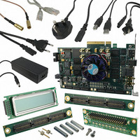
KIT DEVELOPMENT STRATIX IV
Manufacturer
Altera
Series
Stratix® IVr
Type
FPGAr
Datasheets
1.EP4SGX110DF29C3N.pdf
(80 pages)
2.EP4SGX110DF29C3N.pdf
(1154 pages)
3.DK-DEV-4SGX230N.pdf
(2 pages)
4.DK-DEV-4SGX530N.pdf
(57 pages)
Specifications of DK-DEV-4SGX230N
Contents
Development Board, Universal Power Supply, Cables and Software
Silicon Manufacturer
Altera
Core Architecture
FPGA
Core Sub-architecture
Stratix
Silicon Core Number
EP4S
Silicon Family Name
Stratix IV GX
Rohs Compliant
Yes
For Use With/related Products
EP4SGX230K
Lead Free Status / RoHS Status
Lead free / RoHS Compliant
Other names
544-2594
Available stocks
Company
Part Number
Manufacturer
Quantity
Price
Company:

Part Number:
DK-DEV-4SGX230N
Manufacturer:
Altera
Quantity:
135


1–56
Stratix IV Device Handbook Volume 2: Transceivers
f
1
In LTD mode, the CDR uses a phase detector to keep the recovered clock
phase-matched to the data. If the CDR does not stay locked to data due to frequency
drift or severe amplitude attenuation, the LTR/LTD controller switches the CDR back
to LTR mode to lock to the input reference clock. In automatic lock mode, the
LTR/LTD controller switches the CDR from LTD to LTR mode when the following
conditions are met:
■
■
The switch from LTD to LTR mode is indicated by the de-assertion of the
rx_freqlocked signal.
In automatic lock mode, the LTR/LTD controller relies on the PPM detector and the
phase relationship detector to set the CDR in LTR or LTD mode. The PPM detector
and phase relationship detector reaction times can be too long for some applications
that require faster CDR lock time. You can manually control the CDR to reduce its lock
time using the rx_locktorefclk and rx_locktodata ports. In manual lock mode, the
LTR/LTD controller sets the CDR in LTR or LTD mode depending on the logic level
on the rx_locktorefclk and rx_locktodata signals.
When the rx_locktorefclk signal is asserted high, the LTR/LTD controller forces the
CDR to lock to the reference clock. When the rx_locktodata signal is asserted high, it
forces the CDR to lock to data. When both signals are asserted, the rx_locktodata
signal takes precedence over the rx_locktorefclk signal, forcing the CDR to lock to
data.
When the rx_locktorefclk signal is asserted high, the rx_freqlocked signal does not
have any significance and is always driven low, indicating that the CDR is in LTR
mode. When the rx_locktodata signal is asserted high, the rx_freqlocked signal is
always driven high, indicating that the CDR is in LTD mode. If both signals are de-
asserted, the CDR is in automatic lock mode.
The Altera-recommended transceiver reset sequence varies depending on the CDR
lock mode.
For more information about reset sequence recommendations, refer to the
Control and Power Down in Stratix IV Devices
As silicon progresses towards smaller process nodes, the performance of circuits at
these smaller nodes depends more on process variations. These process variations
result in analog voltages that can be offset from the required ranges. Offset
cancellation logic corrects these offsets. The receiver buffer and receiver CDR require
offset cancellation.
Signal threshold detection circuitry indicates the absence of valid signal levels at
the receiver input buffer
■
The CDR output clock is not within the configured PPM frequency threshold
setting with respect to the input reference clock
Offset Cancellation in the Receiver Buffer and Receiver CDR
Valid for PCIe mode only. This condition is defaulted to true for all other
modes.
Manual Lock Mode
Chapter 1: Transceiver Architecture in Stratix IV Devices
chapter.
February 2011 Altera Corporation
Transceiver Block Architecture
Reset
Related parts for DK-DEV-4SGX230N
Image
Part Number
Description
Manufacturer
Datasheet
Request
R

Part Number:
Description:
KIT DEV ARRIA II GX FPGA 2AGX125
Manufacturer:
Altera
Datasheet:

Part Number:
Description:
KIT DEV CYCLONE III LS EP3CLS200
Manufacturer:
Altera
Datasheet:

Part Number:
Description:
KIT DEV STRATIX IV FPGA 4SE530
Manufacturer:
Altera
Datasheet:

Part Number:
Description:
KIT DEV FPGA 2AGX260 W/6.375G TX
Manufacturer:
Altera
Datasheet:

Part Number:
Description:
KIT DEV MAX V 5M570Z
Manufacturer:
Altera
Datasheet:

Part Number:
Description:
KIT DEV STRATIX V FPGA 5SGXEA7
Manufacturer:
Altera
Datasheet:

Part Number:
Description:
KIT DEVELOPMENT STRATIX III
Manufacturer:
Altera
Datasheet:

Part Number:
Description:
KIT DEV ARRIA GX 1AGX60N
Manufacturer:
Altera
Datasheet:
Part Number:
Description:
KIT STARTER CYCLONE IV GX
Manufacturer:
Altera
Datasheet:
Part Number:
Description:
KIT DEVELOPMENT STRATIX IV
Manufacturer:
Altera
Datasheet:

Part Number:
Description:
CPLD, EP610 Family, ECMOS Process, 300 Gates, 16 Macro Cells, 16 Reg., 16 User I/Os, 5V Supply, 35 Speed Grade, 24DIP
Manufacturer:
Altera Corporation
Datasheet:
Part Number:
Description:
CPLD, EP610 Family, ECMOS Process, 300 Gates, 16 Macro Cells, 16 Reg., 16 User I/Os, 5V Supply, 15 Speed Grade, 24DIP
Manufacturer:
Altera Corporation
Datasheet: