DK-DEV-4SGX230N Altera, DK-DEV-4SGX230N Datasheet - Page 832
DK-DEV-4SGX230N
Manufacturer Part Number
DK-DEV-4SGX230N
Description
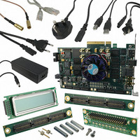
KIT DEVELOPMENT STRATIX IV
Manufacturer
Altera
Series
Stratix® IVr
Type
FPGAr
Datasheets
1.EP4SGX110DF29C3N.pdf
(80 pages)
2.EP4SGX110DF29C3N.pdf
(1154 pages)
3.DK-DEV-4SGX230N.pdf
(2 pages)
4.DK-DEV-4SGX530N.pdf
(57 pages)
Specifications of DK-DEV-4SGX230N
Contents
Development Board, Universal Power Supply, Cables and Software
Silicon Manufacturer
Altera
Core Architecture
FPGA
Core Sub-architecture
Stratix
Silicon Core Number
EP4S
Silicon Family Name
Stratix IV GX
Rohs Compliant
Yes
For Use With/related Products
EP4SGX230K
Lead Free Status / RoHS Status
Lead free / RoHS Compliant
Other names
544-2594
Available stocks
Company
Part Number
Manufacturer
Quantity
Price
Company:

Part Number:
DK-DEV-4SGX230N
Manufacturer:
Altera
Quantity:
135


4–26
Figure 4–14. Identical Channels
Stratix IV Device Handbook Volume 2: Transceivers
locked
Transmitter Side User Logic
in the FPGA Fabric
Transmitter Only Channel with a PLL_L/R
The Basic (PMA Direct) mode configuration that requires a PLL_L/R is one where
each channel in PMA-Direct mode is identical.
identical channels.
c0
Identical channels have the following same configuration:
■
■
■
■
Figure 4–15
Only channels in Basic (PMA Direct) Drive x4 functional mode with a PLL_L/R.
As shown in
Drive functional mode with a PLL_L/R configuration, follow these reset steps:
1. After power up, assert pll_powerdown for a minimum of t
2. After the transmitter PLL locks, as indicated by the pll_locked signal going high
3. After the PLL_L/R locks, as indicated by the locked signal going high (marker 4),
Same effective data rate
Same transmitter local clock divider settings in each channel
Same FPGA fabric-to-transceiver interface data path width
The transmitter channels must receive the high-speed clock from the same PLL
(either CMU PLL or ATX PLL).
between markers 1 and 2).
(marker 3), wait for the locked signal to be asserted. The locked signal is an output
of the PLL_L/R.
the transmitter is ready to accept parallel data from the FPGA fabric and
subsequently transmitting serial data reliably.
Left and Right PLL
(ALTPLL)
shows an example reset sequence timing diagram of four Transmitter
Figure
tx_datain[9:0]
inclk0
4–15, for the Transmitter Only channel in Basic (PMA Direct)
pll_locked
tx_clkout
refclk
Chapter 4: Reset Control and Power Down in Stratix IV Devices
Transmitter Channels in Basic
CMU Channel configured
for clock generation
(PMA Direct) Mode
CH0 (2.5 Gbps)
CH2 (2.5 Gbps)
CH1 (2.5 Gbps)
CH3 (2.5 Gbps)
Figure 4–14
(2.5 Gbps)
PMA Direct Drive Mode Reset Sequences
shows a simple set up of
February 2011 Altera Corporation
pll_powerdown
High-Speed
Serial Clock
(the time
Related parts for DK-DEV-4SGX230N
Image
Part Number
Description
Manufacturer
Datasheet
Request
R

Part Number:
Description:
KIT DEV ARRIA II GX FPGA 2AGX125
Manufacturer:
Altera
Datasheet:

Part Number:
Description:
KIT DEV CYCLONE III LS EP3CLS200
Manufacturer:
Altera
Datasheet:

Part Number:
Description:
KIT DEV STRATIX IV FPGA 4SE530
Manufacturer:
Altera
Datasheet:

Part Number:
Description:
KIT DEV FPGA 2AGX260 W/6.375G TX
Manufacturer:
Altera
Datasheet:

Part Number:
Description:
KIT DEV MAX V 5M570Z
Manufacturer:
Altera
Datasheet:

Part Number:
Description:
KIT DEV STRATIX V FPGA 5SGXEA7
Manufacturer:
Altera
Datasheet:

Part Number:
Description:
KIT DEVELOPMENT STRATIX III
Manufacturer:
Altera
Datasheet:

Part Number:
Description:
KIT DEV ARRIA GX 1AGX60N
Manufacturer:
Altera
Datasheet:
Part Number:
Description:
KIT STARTER CYCLONE IV GX
Manufacturer:
Altera
Datasheet:
Part Number:
Description:
KIT DEVELOPMENT STRATIX IV
Manufacturer:
Altera
Datasheet:

Part Number:
Description:
CPLD, EP610 Family, ECMOS Process, 300 Gates, 16 Macro Cells, 16 Reg., 16 User I/Os, 5V Supply, 35 Speed Grade, 24DIP
Manufacturer:
Altera Corporation
Datasheet:
Part Number:
Description:
CPLD, EP610 Family, ECMOS Process, 300 Gates, 16 Macro Cells, 16 Reg., 16 User I/Os, 5V Supply, 15 Speed Grade, 24DIP
Manufacturer:
Altera Corporation
Datasheet: