DK-DEV-4SGX230N Altera, DK-DEV-4SGX230N Datasheet - Page 107
DK-DEV-4SGX230N
Manufacturer Part Number
DK-DEV-4SGX230N
Description
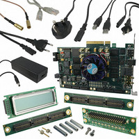
KIT DEVELOPMENT STRATIX IV
Manufacturer
Altera
Series
Stratix® IVr
Type
FPGAr
Datasheets
1.EP4SGX110DF29C3N.pdf
(80 pages)
2.EP4SGX110DF29C3N.pdf
(1154 pages)
3.DK-DEV-4SGX230N.pdf
(2 pages)
4.DK-DEV-4SGX530N.pdf
(57 pages)
Specifications of DK-DEV-4SGX230N
Contents
Development Board, Universal Power Supply, Cables and Software
Silicon Manufacturer
Altera
Core Architecture
FPGA
Core Sub-architecture
Stratix
Silicon Core Number
EP4S
Silicon Family Name
Stratix IV GX
Rohs Compliant
Yes
For Use With/related Products
EP4SGX230K
Lead Free Status / RoHS Status
Lead free / RoHS Compliant
Other names
544-2594
Available stocks
Company
Part Number
Manufacturer
Quantity
Price
Company:

Part Number:
DK-DEV-4SGX230N
Manufacturer:
Altera
Quantity:
135


Chapter 4: DSP Blocks in Stratix IV Devices
Stratix IV Operational Mode Descriptions
February 2011 Altera Corporation
High-Precision Multiplier Adder Mode
Four-multiplier adder mode supports the rounding and saturation logic unit. You can
use the pipeline registers and output registers within the DSP block to pipeline the
multiplier-adder result, increasing the performance of the DSP block.
In a high-precision multiplier adder configuration, shown in
page
precision of 18 x 36 (one two-multiplier adder per half DSP block). This mode is useful
in filtering or FFT applications where a data path greater than 18 bits is required, yet
18 bits is sufficient for the coefficient precision. This can occur where the data has a
high dynamic range. If the coefficients are fixed, as in FFT and most filter applications,
the precision of 18 bits provide a dynamic range over 100 dB, if the largest coefficient
is normalized to the maximum 18-bit representation.
In these situations, the data path can be up to 36 bits, allowing sufficient capacity for
bit growth or gain changes in the signal source without loss of precision. This mode is
also extremely useful in single precision block floating point applications.
The high-precision multiplier adder is performed in two stages. The 18 × 36 multiply
is divided into two 18 × 18 multipliers. The multiplier with the LSB of the data source
is performed unsigned, while the multiplier with the MSB of the data source can be
signed or unsigned. The latter multiplier has its result left shifted by 18 bits prior to
the first adder stage, creating an effective 18 x 36 multiplier. The results of these two
adder blocks are then summed in the second stage adder block to produce the final
result:
Z[54..0] = P
where:
P
P
0
1
= A[17..0] × B[35..0]
= C[17..0] × D[35..0]
4–28, the DSP block can implement 2 two-multiplier adders, with multiplier
0
[53..0] + P
1
[53..0]
Stratix IV Device Handbook Volume 1
Figure 4–18 on
4–27
Related parts for DK-DEV-4SGX230N
Image
Part Number
Description
Manufacturer
Datasheet
Request
R

Part Number:
Description:
KIT DEV ARRIA II GX FPGA 2AGX125
Manufacturer:
Altera
Datasheet:

Part Number:
Description:
KIT DEV CYCLONE III LS EP3CLS200
Manufacturer:
Altera
Datasheet:

Part Number:
Description:
KIT DEV STRATIX IV FPGA 4SE530
Manufacturer:
Altera
Datasheet:

Part Number:
Description:
KIT DEV FPGA 2AGX260 W/6.375G TX
Manufacturer:
Altera
Datasheet:

Part Number:
Description:
KIT DEV MAX V 5M570Z
Manufacturer:
Altera
Datasheet:

Part Number:
Description:
KIT DEV STRATIX V FPGA 5SGXEA7
Manufacturer:
Altera
Datasheet:

Part Number:
Description:
KIT DEVELOPMENT STRATIX III
Manufacturer:
Altera
Datasheet:

Part Number:
Description:
KIT DEV ARRIA GX 1AGX60N
Manufacturer:
Altera
Datasheet:
Part Number:
Description:
KIT STARTER CYCLONE IV GX
Manufacturer:
Altera
Datasheet:
Part Number:
Description:
KIT DEVELOPMENT STRATIX IV
Manufacturer:
Altera
Datasheet:

Part Number:
Description:
CPLD, EP610 Family, ECMOS Process, 300 Gates, 16 Macro Cells, 16 Reg., 16 User I/Os, 5V Supply, 35 Speed Grade, 24DIP
Manufacturer:
Altera Corporation
Datasheet:
Part Number:
Description:
CPLD, EP610 Family, ECMOS Process, 300 Gates, 16 Macro Cells, 16 Reg., 16 User I/Os, 5V Supply, 15 Speed Grade, 24DIP
Manufacturer:
Altera Corporation
Datasheet: