HD6417720BP133BV Renesas Electronics America, HD6417720BP133BV Datasheet - Page 43
HD6417720BP133BV
Manufacturer Part Number
HD6417720BP133BV
Description
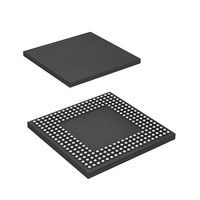
SH3-DSP, WITH USB AND LCDC, PB-F
Manufacturer
Renesas Electronics America
Series
SuperH® SH7700r
Datasheet
1.R8A77210C133BAV.pdf
(1478 pages)
Specifications of HD6417720BP133BV
Core Processor
SH-3 DSP
Core Size
32-Bit
Speed
133MHz
Connectivity
FIFO, I²C, IrDA, MMC, SCI, SD, SIO, SIM, USB
Peripherals
DMA, LCD, POR, WDT
Number Of I /o
117
Program Memory Type
ROMless
Ram Size
16K x 8
Voltage - Supply (vcc/vdd)
1.4 V ~ 1.6 V
Data Converters
A/D 4x10b; D/A 2x8b
Oscillator Type
Internal
Operating Temperature
-20°C ~ 75°C
Package / Case
256-BGA
Lead Free Status / RoHS Status
Lead free / RoHS Compliant
Eeprom Size
-
Program Memory Size
-


Figure 27.4
Figure 27.5
Figure 27.6
Figure 27.7
Figure 27.8
Figure 27.9
Figure 27.10 Analog Input Pin Equivalent Circuit..................................................................... 951
Section 28 D/A Converter (DAC)
Figure 28.1
Figure 28.2
Section 29 PC Card Controller (PCC)
Figure 29.1
Figure 29.2
Figure 29.3
Figure 29.4
Figure 29.5
Figure 29.6
Figure 29.7
Figure 29.8
Figure 29.9
Section 30 SIM Card Module (SIM)
Figure 30.1
Figure 30.2
Figure 30.3
Figure 30.4
Figure 30.5
Figure 30.6
Figure 30.7
Figure 30.8
Figure 30.9
Figure 30.10 Procedure for Stopping Clock and Restarting..................................................... 1024
Figure 30.11 Example of Pin Connections in Smart Card Interface ........................................ 1025
Figure 30.12 TEIE Set Timing................................................................................................. 1026
R01UH0083EJ0400 Rev. 4.00
Sep 21, 2010
D/A Converter Operation Example....................................................................... 956
Data Format Used by Smart Card Interface........................................................ 1007
Receive Data Sampling Timing in Smart Card Mode......................................... 1020
Retransmission when Smart Card Interface is in Receive Mode ........................ 1022
Example of A/D Converter Operation
(Scan Mode, Channels AN0 to AN2 Selected)..................................................... 941
A/D Conversion Timing ....................................................................................... 942
External Trigger Input Timing.............................................................................. 943
Definitions of A/D Conversion Accuracy............................................................. 945
Analog Input Circuit Example .............................................................................. 949
Example of Analog Input Protection Circuit ........................................................ 951
Block Diagram of D/A Converter......................................................................... 953
PC Card Controller Block Diagram ...................................................................... 958
Continuous 32-Mbyte Area Mode ........................................................................ 960
Continuous 16-Mbyte Area Mode (Area 6) .......................................................... 961
Interface ................................................................................................................ 976
PCMCIA Memory Card Interface Basic Timing .................................................. 980
PCMCIA Memory Card Interface Wait Timing ................................................... 981
PCMCIA I/O Card Interface Basic Timing .......................................................... 982
PCMCIA I/O Card Interface Wait Timing............................................................ 983
Dynamic Bus Sizing Timing for PCMCIA I/O Card Interface............................. 984
Smart Card Interface............................................................................................. 988
Examples of Start Character Waveforms............................................................ 1010
Example of Initialization Flow ........................................................................... 1013
Example of Transmit Processing ........................................................................ 1015
Example of Receive Processing.......................................................................... 1017
Retransmit Standby Mode (Clock Stopped)
when Smart Card Interface is in Transmit Mode ................................................ 1023
Page xliii of lx
Related parts for HD6417720BP133BV
Image
Part Number
Description
Manufacturer
Datasheet
Request
R

Part Number:
Description:
KIT STARTER FOR M16C/29
Manufacturer:
Renesas Electronics America
Datasheet:

Part Number:
Description:
KIT STARTER FOR R8C/2D
Manufacturer:
Renesas Electronics America
Datasheet:

Part Number:
Description:
R0K33062P STARTER KIT
Manufacturer:
Renesas Electronics America
Datasheet:

Part Number:
Description:
KIT STARTER FOR R8C/23 E8A
Manufacturer:
Renesas Electronics America
Datasheet:

Part Number:
Description:
KIT STARTER FOR R8C/25
Manufacturer:
Renesas Electronics America
Datasheet:

Part Number:
Description:
KIT STARTER H8S2456 SHARPE DSPLY
Manufacturer:
Renesas Electronics America
Datasheet:

Part Number:
Description:
KIT STARTER FOR R8C38C
Manufacturer:
Renesas Electronics America
Datasheet:

Part Number:
Description:
KIT STARTER FOR R8C35C
Manufacturer:
Renesas Electronics America
Datasheet:

Part Number:
Description:
KIT STARTER FOR R8CL3AC+LCD APPS
Manufacturer:
Renesas Electronics America
Datasheet:
Part Number:
Description:
KIT STARTER FOR RX610
Manufacturer:
Renesas Electronics America
Datasheet:

Part Number:
Description:
KIT STARTER FOR R32C/118
Manufacturer:
Renesas Electronics America
Datasheet:

Part Number:
Description:
KIT DEV RSK-R8C/26-29
Manufacturer:
Renesas Electronics America
Datasheet:

Part Number:
Description:
KIT STARTER FOR SH7124
Manufacturer:
Renesas Electronics America
Datasheet:

Part Number:
Description:
KIT STARTER FOR H8SX/1622
Manufacturer:
Renesas Electronics America
Datasheet:

Part Number:
Description:
KIT DEV FOR SH7203
Manufacturer:
Renesas Electronics America
Datasheet: