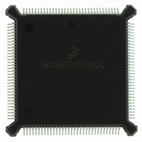
MC68302EH20C Freescale Semiconductor, MC68302EH20C Datasheet - Page 77

MC68302EH20C
Manufacturer Part Number
MC68302EH20C
Description
IC MPU MULTI-PROTOCOL 132-PQFP
Manufacturer
Freescale Semiconductor
Datasheets
1.MC68302AG20C.pdf
(4 pages)
2.MC68302AG20C.pdf
(2 pages)
3.MC68302AG20C.pdf
(13 pages)
4.MC68302EH20C.pdf
(481 pages)
Specifications of MC68302EH20C
Processor Type
M683xx 32-Bit
Speed
20MHz
Voltage
5V
Mounting Type
Surface Mount
Package / Case
132-MQFP, 132-PQFP
Family Name
M68000
Device Core
ColdFire
Device Core Size
32b
Frequency (max)
20MHz
Instruction Set Architecture
RISC
Supply Voltage 1 (typ)
5V
Operating Temp Range
0C to 70C
Operating Temperature Classification
Commercial
Mounting
Surface Mount
Pin Count
132
Package Type
PQFP
Lead Free Status / RoHS Status
Lead free / RoHS Compliant
Features
-
Lead Free Status / Rohs Status
Compliant
Available stocks
Company
Part Number
Manufacturer
Quantity
Price
Company:
Part Number:
MC68302EH20C
Manufacturer:
Freescale Semiconductor
Quantity:
10 000
Part Number:
MC68302EH20C
Manufacturer:
FREESCALE
Quantity:
20 000
Company:
Part Number:
MC68302EH20CB1
Manufacturer:
Freescale Semiconductor
Quantity:
10 000
Company:
Part Number:
MC68302EH20CR2
Manufacturer:
Freescale Semiconductor
Quantity:
10 000
- MC68302AG20C PDF datasheet
- MC68302AG20C PDF datasheet #2
- MC68302AG20C PDF datasheet #3
- MC68302EH20C PDF datasheet #4
- Current page: 77 of 481
- Download datasheet (2Mb)
3.2.5.3 Interrupt Mask Register (IMR)
Each bit in the 16-bit IMR corresponds to an INRQ interrupt source. The user masks an in-
terrupt source by clearing the corresponding bit in the IMR. When a masked INRQ interrupt
occurs, the corresponding bit in the IPR is set, but the IMR bit prevents the interrupt request
from reaching the M68000 core. If an INRQ source is requesting interrupt service when the
user clears the IMR bit, the request to the core will cease, but the IPR bit remains set. If the
IMR bit is then set later by the user, the pending interrupt request will once again request
interrupt service and will be processed by the core according to its assigned priority. The
IMR, which can be read by the user at any time, is cleared by reset.
It is not possible to mask the ERR INRQ source in the IMR. Bit 0 of the IMR is undefined.
MOTOROLA
PB11
PB9
15
7
If a bit in the IMR is masked at the same time that the interrupt
at level 4 is causing the M68000 core to begin the interrupt ac-
knowledge cycle, then the interrupt is not processed, and one of
two possible cases will occur. First, if other unmasked interrupts
are pending at level 4, then the interrupt controller will acknowl-
edge the interrupt with a vector from the next highest priority un-
masked interrupt source. Second, if no other interrupts are
pending at level 4, then the interrupt controller will acknowledge
the interrupt with the error vector (00000 binary).
To avoid handling the error vector, the user can raise the inter-
rupt mask in the M68000 core status register (SR) to 4 before
masking the interrupt source and then lower the level back to its
original value. Also, if the interrupt source has multiple events
(e.g., SCC1), then the interrupts for that peripheral can be
masked within the peripheral mask register.
To clear bits that were set by multiple interrupt events, the user
should clear all the unmasked events in the corresponding on-
chip peripheral's event register.
TIMER2
PB10
14
6
SCC1
SCP
13
5
MC68302 USER’S MANUAL
TIMER3
SDMA
12
4
NOTE
NOTE
SMC1
IDMA
11
3
SMC2
SCC2
10
2
System Integration Block (SIB)
TIMER1
PB8
9
1
SCC3
—
8
0
3-27
Related parts for MC68302EH20C
Image
Part Number
Description
Manufacturer
Datasheet
Request
R
Part Number:
Description:
Manufacturer:
Freescale Semiconductor, Inc
Datasheet:

Part Number:
Description:
MC68302 Configuring the Chip Selects on the MC68302
Manufacturer:
Motorola / Freescale Semiconductor

Part Number:
Description:
MC68302 Design Concept - Expanding Interrupts on the MC68302
Manufacturer:
Motorola / Freescale Semiconductor

Part Number:
Description:
MC68302 MC68302 Adapting a WAN Controller to a LAN Environment
Manufacturer:
Motorola / Freescale Semiconductor

Part Number:
Description:
MC68302 EKB Applications - Power Measurements on the MC68302
Manufacturer:
Motorola / Freescale Semiconductor

Part Number:
Description:
MC68302 Interfacing the MC68020 to a Slave MC68302
Manufacturer:
Motorola / Freescale Semiconductor

Part Number:
Description:
MC68302 MC68302 Software Performance
Manufacturer:
Motorola / Freescale Semiconductor

Part Number:
Description:
MC68302 Evaluating EDX on the ADS302
Manufacturer:
Motorola / Freescale Semiconductor

Part Number:
Description:
MC68302 Design Advisory #1 - MC68SC302 Passive ISDN Protocol Engine
Manufacturer:
Motorola / Freescale Semiconductor

Part Number:
Description:
MC68302, MC68360, and MPC860 Characteristics and Design Notes for Crystal Feedback Oscillators
Manufacturer:
Motorola / Freescale Semiconductor
Part Number:
Description:
Mc68302 Integrated Multi-protocol Processor
Manufacturer:
Freescale Semiconductor, Inc
Datasheet:
Part Number:
Description:
Manufacturer:
Freescale Semiconductor, Inc
Datasheet:
Part Number:
Description:
Manufacturer:
Freescale Semiconductor, Inc
Datasheet:
Part Number:
Description:
Manufacturer:
Freescale Semiconductor, Inc
Datasheet:
Part Number:
Description:
Manufacturer:
Freescale Semiconductor, Inc
Datasheet:


