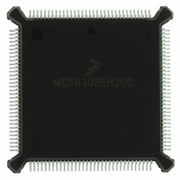
MC68302EH20C Freescale Semiconductor, MC68302EH20C Datasheet - Page 238

MC68302EH20C
Manufacturer Part Number
MC68302EH20C
Description
IC MPU MULTI-PROTOCOL 132-PQFP
Manufacturer
Freescale Semiconductor
Datasheets
1.MC68302AG20C.pdf
(4 pages)
2.MC68302AG20C.pdf
(2 pages)
3.MC68302AG20C.pdf
(13 pages)
4.MC68302EH20C.pdf
(481 pages)
Specifications of MC68302EH20C
Processor Type
M683xx 32-Bit
Speed
20MHz
Voltage
5V
Mounting Type
Surface Mount
Package / Case
132-MQFP, 132-PQFP
Family Name
M68000
Device Core
ColdFire
Device Core Size
32b
Frequency (max)
20MHz
Instruction Set Architecture
RISC
Supply Voltage 1 (typ)
5V
Operating Temp Range
0C to 70C
Operating Temperature Classification
Commercial
Mounting
Surface Mount
Pin Count
132
Package Type
PQFP
Lead Free Status / RoHS Status
Lead free / RoHS Compliant
Features
-
Lead Free Status / Rohs Status
Compliant
Available stocks
Company
Part Number
Manufacturer
Quantity
Price
Company:
Part Number:
MC68302EH20C
Manufacturer:
Freescale Semiconductor
Quantity:
10 000
Part Number:
MC68302EH20C
Manufacturer:
FREESCALE
Quantity:
20 000
Company:
Part Number:
MC68302EH20CB1
Manufacturer:
Freescale Semiconductor
Quantity:
10 000
Company:
Part Number:
MC68302EH20CR2
Manufacturer:
Freescale Semiconductor
Quantity:
10 000
- MC68302AG20C PDF datasheet
- MC68302AG20C PDF datasheet #2
- MC68302AG20C PDF datasheet #3
- MC68302EH20C PDF datasheet #4
- Current page: 238 of 481
- Download datasheet (2Mb)
Communications Processor (CP)
The V.110 controller operates on the ISDN physical interface using either IDL or GCI (IOM-
2) over one of the B channels. NMSI and PCM physical interfaces are also possible. The
data synchronization register (DSR) should be programmed to 'xxxxxxx1 00000000'b to
achieve the proper frame synchronization (see 4.5.4 SCC Data Synchronization Register
(DSR)).
4.5.15.5 V.110 Programming Model
The M68000 core configures each SCC to operate in one of the protocols by the MODE1–
MODE0 bits in the SCC mode register. If MODE1–MODE0 = 10, the synchronous link DDC-
MP protocol is selected. The V.110 bit should also be set in the DDCMP mode register. The
V.110 controller uses the same basic data structure as the DDCMP controller, the same
command set, and the same event and mask registers for interrupt generation.
4.5.15.6 Error-Handling Procedure
The V.110 controller reports frame reception and transmission error conditions using the
channel buffer descriptors (BDs) and the V.110 event register.
Transmission Errors:
Reception Errors:
4.5.15.7 V.110 Receive Buffer Descriptor (Rx BD)
The CP reports information about the received data for each buffer using the BDs. The Rx
BD is shown in Figure 4-40. The CP closes the current buffer, generates a maskable inter-
rupt, and starts to receive data in the next buffer after any of the following events:
4-118
1. Transmitter Underrun. When this error occurs, the channel terminates buffer transmis-
1. Overrun Error. The V.110 controller maintains an internal three-byte length FIFO for
2. Synchronization Error. A synchronization error is detected by the V.110 controller
• Receiving of 10 bytes (80-bit frame)
• Detecting of an error
• Issuing the ENTER HUNT MODE command
sion, closes the buffer, sets the underrun (UN) bit in the BD, and generates the trans-
mit error (TXE) interrupt (if enabled). The channel will resume transmission after the
reception of the RESTART TRANSMIT command. The FIFO size is three bytes.
receiving data. When the receive FIFO overrun error occurs, the channel writes the
received data byte to the internal FIFO on top of the previously received byte (the pre-
vious data byte is lost). Then the channel closes the buffer, sets the overflow (OV) bit
in the BD, and generates the receive frame (RXF) interrupt (if enabled). The channel
will automatically enter hunt mode.
when the MSB of every byte is not one. When this error occurs, the channel writes the
received byte to the buffer and continues to receive the V.110 frame. When the frame
ends, the channel closes the buffer, sets the synchronization error (SE) bit in the BD,
and generates the RXF interrupt (if enabled). The channel will automatically enter the
hunt mode.
MC68302 USER’S MANUAL
MOTOROLA
Related parts for MC68302EH20C
Image
Part Number
Description
Manufacturer
Datasheet
Request
R
Part Number:
Description:
Manufacturer:
Freescale Semiconductor, Inc
Datasheet:

Part Number:
Description:
MC68302 Configuring the Chip Selects on the MC68302
Manufacturer:
Motorola / Freescale Semiconductor

Part Number:
Description:
MC68302 Design Concept - Expanding Interrupts on the MC68302
Manufacturer:
Motorola / Freescale Semiconductor

Part Number:
Description:
MC68302 MC68302 Adapting a WAN Controller to a LAN Environment
Manufacturer:
Motorola / Freescale Semiconductor

Part Number:
Description:
MC68302 EKB Applications - Power Measurements on the MC68302
Manufacturer:
Motorola / Freescale Semiconductor

Part Number:
Description:
MC68302 Interfacing the MC68020 to a Slave MC68302
Manufacturer:
Motorola / Freescale Semiconductor

Part Number:
Description:
MC68302 MC68302 Software Performance
Manufacturer:
Motorola / Freescale Semiconductor

Part Number:
Description:
MC68302 Evaluating EDX on the ADS302
Manufacturer:
Motorola / Freescale Semiconductor

Part Number:
Description:
MC68302 Design Advisory #1 - MC68SC302 Passive ISDN Protocol Engine
Manufacturer:
Motorola / Freescale Semiconductor

Part Number:
Description:
MC68302, MC68360, and MPC860 Characteristics and Design Notes for Crystal Feedback Oscillators
Manufacturer:
Motorola / Freescale Semiconductor
Part Number:
Description:
Mc68302 Integrated Multi-protocol Processor
Manufacturer:
Freescale Semiconductor, Inc
Datasheet:
Part Number:
Description:
Manufacturer:
Freescale Semiconductor, Inc
Datasheet:
Part Number:
Description:
Manufacturer:
Freescale Semiconductor, Inc
Datasheet:
Part Number:
Description:
Manufacturer:
Freescale Semiconductor, Inc
Datasheet:
Part Number:
Description:
Manufacturer:
Freescale Semiconductor, Inc
Datasheet:


