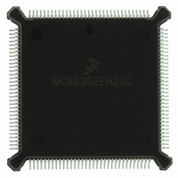
MC68302EH20C Freescale Semiconductor, MC68302EH20C Datasheet - Page 206

MC68302EH20C
Manufacturer Part Number
MC68302EH20C
Description
IC MPU MULTI-PROTOCOL 132-PQFP
Manufacturer
Freescale Semiconductor
Datasheets
1.MC68302AG20C.pdf
(4 pages)
2.MC68302AG20C.pdf
(2 pages)
3.MC68302AG20C.pdf
(13 pages)
4.MC68302EH20C.pdf
(481 pages)
Specifications of MC68302EH20C
Processor Type
M683xx 32-Bit
Speed
20MHz
Voltage
5V
Mounting Type
Surface Mount
Package / Case
132-MQFP, 132-PQFP
Family Name
M68000
Device Core
ColdFire
Device Core Size
32b
Frequency (max)
20MHz
Instruction Set Architecture
RISC
Supply Voltage 1 (typ)
5V
Operating Temp Range
0C to 70C
Operating Temperature Classification
Commercial
Mounting
Surface Mount
Pin Count
132
Package Type
PQFP
Lead Free Status / RoHS Status
Lead free / RoHS Compliant
Features
-
Lead Free Status / Rohs Status
Compliant
Available stocks
Company
Part Number
Manufacturer
Quantity
Price
Company:
Part Number:
MC68302EH20C
Manufacturer:
Freescale Semiconductor
Quantity:
10 000
Part Number:
MC68302EH20C
Manufacturer:
FREESCALE
Quantity:
20 000
Company:
Part Number:
MC68302EH20CB1
Manufacturer:
Freescale Semiconductor
Quantity:
10 000
Company:
Part Number:
MC68302EH20CR2
Manufacturer:
Freescale Semiconductor
Quantity:
10 000
- MC68302AG20C PDF datasheet
- MC68302AG20C PDF datasheet #2
- MC68302AG20C PDF datasheet #3
- MC68302EH20C PDF datasheet #4
- Current page: 206 of 481
- Download datasheet (2Mb)
Communications Processor (CP)
Memory Map for the placement of the three SCC parameter RAM areas and Table 4-5 for
the other parameter RAM values.
The M68000 core configures each SCC to operate in one of four protocols by the MODE1–
MODE0 bits in the SCC mode register. MODE1–MODE0 = 11 selects the BISYNC mode of
operation. The SYN1–SYN2 synchronization characters are programmed in the data syn-
chronization register (see 4.5.4 SCC Data Synchronization Register (DSR)).
The BISYNC controller uses the same basic data structure as the other protocol controllers.
Receive and transmit errors are reported through their respective BDs. The status of the line
is reflected in the SCC status register, and a maskable interrupt is generated upon each sta-
tus change.
There are two basic ways of handling the BISYNC channels. First, data may be inspected
on a per-byte basis, with the BISYNC controller interrupting the M68000 core upon receipt
of every byte of data. Second, the BISYNC controller may be operated so that software is
only necessary for handling the first two to three bytes of data; subsequent data (until the
end of the block) can be handled by the BISYNC controller without interrupting the M68000
core. See 4.5.13.14 Programming the BISYNC Controllers for more information.
4.5.13.4 BISYNC Command Set
The following commands are issued to the command register.
STOP TRANSMIT Command
4-86
SCC Base + 9C
SCC Base + 9E
SCC Base + A0 #
SCC Base + A2
SCC Base + A4 #
SCC Base + A6
SCC Base + A8
SCC Base + AA #
SCC Base + AC #
SCC Base + AE #
SCC Base + B0 #
SCC Base + B2 #
SCC Base + B4 #
SCC Base + B6 #
SCC Base + B8 #
SCC Base + BA #
SCC Base + BC #
SCC Base + BE #
After a hardware or software reset and the enabling of the channel using the SCC mode
register, the channel is in the transmit enable mode and starts polling the first BD in the
table approximately every eight transmit clocks.
The STOP TRANSMIT command aborts transmission after the contents of the FIFO are
transmitted (up to three bytes) without waiting until the end of the buffer is reached. The
TBD# is not advanced. SYNC characters consisting of SYNC-SYNC or DLE-SYNC pairs
(according to the transmitter mode) will be continually transmitted until transmission is re-
enabled by issuing the RESTART TRANSMIT command. The STOP TRANSMIT com-
# Initialized by the user (M68000 core).
Address
Table 4-9. BISYNC Specific Parameter RAM
CHARACTER2
CHARACTER3
CHARACTER4
CHARACTER5
CHARACTER6
CHARACTER7
CHARACTER8
CHARACTER1
PRCRC
PTCRC
BSYNC
PAREC
CRCC
TCRC
Name
RCRC
BDLE
RES
RES
MC68302 USER’S MANUAL
Width
Word
Word
Word
Word
Word
Word
Word
Word
Word
Word
Word
Word
Word
Word
Word
Word
Word
Word
Temp Receive CRC
CRC Constant
Preset Receiver CRC 16/LRC
Temp Transmit CRC
Preset Transmitter CRC 16/LRC
Reserved
Reserved
Receive Parity Error Counter
BISYNC SYNC Character
BISYNC DLE Character
CONTROL Character 1
CONTROL Character 2
CONTROL Character 3
CONTROL Character 4
CONTROL Character 5
CONTROL Character 6
CONTROL Character 7
CONTROL Character 8
Description
MOTOROLA
Related parts for MC68302EH20C
Image
Part Number
Description
Manufacturer
Datasheet
Request
R
Part Number:
Description:
Manufacturer:
Freescale Semiconductor, Inc
Datasheet:

Part Number:
Description:
MC68302 Configuring the Chip Selects on the MC68302
Manufacturer:
Motorola / Freescale Semiconductor

Part Number:
Description:
MC68302 Design Concept - Expanding Interrupts on the MC68302
Manufacturer:
Motorola / Freescale Semiconductor

Part Number:
Description:
MC68302 MC68302 Adapting a WAN Controller to a LAN Environment
Manufacturer:
Motorola / Freescale Semiconductor

Part Number:
Description:
MC68302 EKB Applications - Power Measurements on the MC68302
Manufacturer:
Motorola / Freescale Semiconductor

Part Number:
Description:
MC68302 Interfacing the MC68020 to a Slave MC68302
Manufacturer:
Motorola / Freescale Semiconductor

Part Number:
Description:
MC68302 MC68302 Software Performance
Manufacturer:
Motorola / Freescale Semiconductor

Part Number:
Description:
MC68302 Evaluating EDX on the ADS302
Manufacturer:
Motorola / Freescale Semiconductor

Part Number:
Description:
MC68302 Design Advisory #1 - MC68SC302 Passive ISDN Protocol Engine
Manufacturer:
Motorola / Freescale Semiconductor

Part Number:
Description:
MC68302, MC68360, and MPC860 Characteristics and Design Notes for Crystal Feedback Oscillators
Manufacturer:
Motorola / Freescale Semiconductor
Part Number:
Description:
Mc68302 Integrated Multi-protocol Processor
Manufacturer:
Freescale Semiconductor, Inc
Datasheet:
Part Number:
Description:
Manufacturer:
Freescale Semiconductor, Inc
Datasheet:
Part Number:
Description:
Manufacturer:
Freescale Semiconductor, Inc
Datasheet:
Part Number:
Description:
Manufacturer:
Freescale Semiconductor, Inc
Datasheet:
Part Number:
Description:
Manufacturer:
Freescale Semiconductor, Inc
Datasheet:


