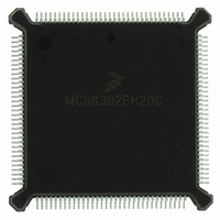
MC68302EH20C Freescale Semiconductor, MC68302EH20C Datasheet - Page 188

MC68302EH20C
Manufacturer Part Number
MC68302EH20C
Description
IC MPU MULTI-PROTOCOL 132-PQFP
Manufacturer
Freescale Semiconductor
Datasheets
1.MC68302AG20C.pdf
(4 pages)
2.MC68302AG20C.pdf
(2 pages)
3.MC68302AG20C.pdf
(13 pages)
4.MC68302EH20C.pdf
(481 pages)
Specifications of MC68302EH20C
Processor Type
M683xx 32-Bit
Speed
20MHz
Voltage
5V
Mounting Type
Surface Mount
Package / Case
132-MQFP, 132-PQFP
Family Name
M68000
Device Core
ColdFire
Device Core Size
32b
Frequency (max)
20MHz
Instruction Set Architecture
RISC
Supply Voltage 1 (typ)
5V
Operating Temp Range
0C to 70C
Operating Temperature Classification
Commercial
Mounting
Surface Mount
Pin Count
132
Package Type
PQFP
Lead Free Status / RoHS Status
Lead free / RoHS Compliant
Features
-
Lead Free Status / Rohs Status
Compliant
Available stocks
Company
Part Number
Manufacturer
Quantity
Price
Company:
Part Number:
MC68302EH20C
Manufacturer:
Freescale Semiconductor
Quantity:
10 000
Part Number:
MC68302EH20C
Manufacturer:
FREESCALE
Quantity:
20 000
Company:
Part Number:
MC68302EH20CB1
Manufacturer:
Freescale Semiconductor
Quantity:
10 000
Company:
Part Number:
MC68302EH20CR2
Manufacturer:
Freescale Semiconductor
Quantity:
10 000
- MC68302AG20C PDF datasheet
- MC68302AG20C PDF datasheet #2
- MC68302AG20C PDF datasheet #3
- MC68302EH20C PDF datasheet #4
- Current page: 188 of 481
- Download datasheet (2Mb)
Communications Processor (CP)
4.5.12.1 HDLC Channel Frame Transmission Processing
The HDLC transmitter is designed to work with almost no intervention from the M68000
core. When the M68000 core enables one of the transmitters, it will start transmitting flags
or idles as programmed in the HDLC mode register. The HDLC controller will poll the first
buffer descriptor (BD) in the transmit channel's BD table. When there is a frame to transmit,
the HDLC controller will fetch the data from memory and start transmitting the frame (after
first transmitting the user-specified minimum number of flags between frames). When the
end of the current BD has been reached and the last buffer in the frame bit is set, the cyclic
redundancy check (CRC), if selected, and the closing flag are appended.
Following the transmission of the closing flag, the HDLC controller writes the frame status
bits into the BD and clears the ready bit. When the end of the current BD has been reached,
and the last bit is not set (working in multibuffer mode), only the ready bit is cleared. In either
mode, an interrupt is issued according to the interrupt bit in the BD. The HDLC controller will
then proceed to the next BD in the table. In this way, the user may be interrupted after each
buffer, after a specific buffer has been transmitted, or after each frame.
To rearrange the transmit queue before the IMP has completed transmission of all buffers,
issue the STOP TRANSMIT command. This technique can be useful for transmitting expe-
dited data before previously linked buffers or for error situations. When receiving the STOP
TRANSMIT command, the HDLC controller will abort the current frame being transmitted
and start transmitting idles or flags. When the HDLC controller is given the RESTART
TRANSMIT command, it resumes transmission.
4.5.12.2 HDLC Channel Frame Reception Processing
The HDLC receiver is also designed to work with almost no intervention from the M68000
core. The HDLC receiver can perform address recognition, CRC checking, and maximum
frame length checking. The received frame (all fields between the opening and closing flags)
is made available to the user for performing any HDLC-based protocol.
When the M68000 core enables one of the receivers, the receiver waits for an opening flag
character. When the receiver detects the first byte of the frame, the HDLC controller will
compare the frame address against the user-programmable addresses. The user has four
16-bit address registers and an address mask available for address matching. The HDLC
controller will compare the received address field to the user-defined values after masking
with the address mask. The HDLC controller can also detect broadcast (all ones) addressed
frames, if one address register is written with all ones.
If a match is detected, the HDLC controller will fetch the next BD and, if empty, will start to
transfer the incoming frame to the BD's associated data buffer starting with the first address
byte. When the data buffer has been filled, the HDLC controller clears the empty bit in the
BD and generates an interrupt if the interrupt bit in the BD is set. If the incoming frame ex-
4-68
• Detection of Non-Octet Aligned Frames
• Detection of Frames That Are Too Long
• Programmable Flags (0–15) between Successive Frames
• Automatic Retransmission in Case of Collision
MC68302 USER’S MANUAL
MOTOROLA
Related parts for MC68302EH20C
Image
Part Number
Description
Manufacturer
Datasheet
Request
R
Part Number:
Description:
Manufacturer:
Freescale Semiconductor, Inc
Datasheet:

Part Number:
Description:
MC68302 Configuring the Chip Selects on the MC68302
Manufacturer:
Motorola / Freescale Semiconductor

Part Number:
Description:
MC68302 Design Concept - Expanding Interrupts on the MC68302
Manufacturer:
Motorola / Freescale Semiconductor

Part Number:
Description:
MC68302 MC68302 Adapting a WAN Controller to a LAN Environment
Manufacturer:
Motorola / Freescale Semiconductor

Part Number:
Description:
MC68302 EKB Applications - Power Measurements on the MC68302
Manufacturer:
Motorola / Freescale Semiconductor

Part Number:
Description:
MC68302 Interfacing the MC68020 to a Slave MC68302
Manufacturer:
Motorola / Freescale Semiconductor

Part Number:
Description:
MC68302 MC68302 Software Performance
Manufacturer:
Motorola / Freescale Semiconductor

Part Number:
Description:
MC68302 Evaluating EDX on the ADS302
Manufacturer:
Motorola / Freescale Semiconductor

Part Number:
Description:
MC68302 Design Advisory #1 - MC68SC302 Passive ISDN Protocol Engine
Manufacturer:
Motorola / Freescale Semiconductor

Part Number:
Description:
MC68302, MC68360, and MPC860 Characteristics and Design Notes for Crystal Feedback Oscillators
Manufacturer:
Motorola / Freescale Semiconductor
Part Number:
Description:
Mc68302 Integrated Multi-protocol Processor
Manufacturer:
Freescale Semiconductor, Inc
Datasheet:
Part Number:
Description:
Manufacturer:
Freescale Semiconductor, Inc
Datasheet:
Part Number:
Description:
Manufacturer:
Freescale Semiconductor, Inc
Datasheet:
Part Number:
Description:
Manufacturer:
Freescale Semiconductor, Inc
Datasheet:
Part Number:
Description:
Manufacturer:
Freescale Semiconductor, Inc
Datasheet:


