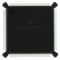
MC68302EH20C Freescale Semiconductor, MC68302EH20C Datasheet - Page 445

MC68302EH20C
Manufacturer Part Number
MC68302EH20C
Description
IC MPU MULTI-PROTOCOL 132-PQFP
Manufacturer
Freescale Semiconductor
Datasheets
1.MC68302AG20C.pdf
(4 pages)
2.MC68302AG20C.pdf
(2 pages)
3.MC68302AG20C.pdf
(13 pages)
4.MC68302EH20C.pdf
(481 pages)
Specifications of MC68302EH20C
Processor Type
M683xx 32-Bit
Speed
20MHz
Voltage
5V
Mounting Type
Surface Mount
Package / Case
132-MQFP, 132-PQFP
Family Name
M68000
Device Core
ColdFire
Device Core Size
32b
Frequency (max)
20MHz
Instruction Set Architecture
RISC
Supply Voltage 1 (typ)
5V
Operating Temp Range
0C to 70C
Operating Temperature Classification
Commercial
Mounting
Surface Mount
Pin Count
132
Package Type
PQFP
Lead Free Status / RoHS Status
Lead free / RoHS Compliant
Features
-
Lead Free Status / Rohs Status
Compliant
Available stocks
Company
Part Number
Manufacturer
Quantity
Price
Company:
Part Number:
MC68302EH20C
Manufacturer:
Freescale Semiconductor
Quantity:
10 000
Part Number:
MC68302EH20C
Manufacturer:
FREESCALE
Quantity:
20 000
Company:
Part Number:
MC68302EH20CB1
Manufacturer:
Freescale Semiconductor
Quantity:
10 000
Company:
Part Number:
MC68302EH20CR2
Manufacturer:
Freescale Semiconductor
Quantity:
10 000
- MC68302AG20C PDF datasheet
- MC68302AG20C PDF datasheet #2
- MC68302AG20C PDF datasheet #3
- MC68302EH20C PDF datasheet #4
- Current page: 445 of 481
- Download datasheet (2Mb)
TX—Tx Buffer
RX—Rx Buffer
E.2.1.2.5 UART Mask Register (SCCM). This 8-bit register is located at offset $88A
(SCC1), $89A (SCC2), and $8AA (SCC3) on D15-D8 of a 16-bit data bus. The SCCM is
used to enable and disable interrupt events reported by the SCCE. The mask bits corre-
spond to the interrupt event bit shown in the SCCE. A bit should be set to one to enable the
corresponding interrupt in the SCCE.
E.2.1.2.6 UART Status Register (SCCS). This 8-bit register is located at offset $88C
(SCC1), $89C (SCC2), and $8AC (SCC3), on D15-D8 of a 16-bit data bus. The SCCS reg-
ister reflects the current status of the RXD, CD, and CTS lines as seen by the SCC.
ID—Idle Status on the Receiver Line (valid only when the ENR bit is set and the receive
clock is running)
CD—Carrier Detect Status Changed (valid only when the ENR bit is set and the receive
clock is running)
CTS—Clear-To-Send Status Changed (valid only when the ENT bit is set and the transmit
clock is running)
E.2.1.3 GENERAL AND UART PROTOCOL-SPECIFIC PARAMETER RAM. Each SCC
has 32 words of parameter RAM used to configure receive and transmit operation, store
temporary parameters for the CP, and maintain counters. The first 14 words are general
parameters, which are the same for each protocol. The last 18 words are specific to the pro-
tocol selected. The following sections discuss the parameters that the user must initialize to
configure the UART operation.
MOTOROLA
0 = No interrupt.
1 = A buffer has been transmitted on the UART channel (set only if the I bit in the Tx
0 = No interrupt.
1 = A buffer was received on the UART channel (set only if the I bit in the Rx buffer
0 = Receiver Line is not idling.
1 = Either CD is not asserted or the receiver line is idling while CD is asserted.
0 = CD is asserted.
1 = CD is not asserted.
0 = CTS is asserted.
1 = CTS is not asserted.
buffer descriptor is set).
descriptor is set).
CTS
—
7
7
CD
—
6
6
MC68360 USER’S MANUAL
IDL
—
5
5
BRK
—
4
4
CCR
—
3
3
BSY
ID
2
2
CD
TX
1
1
CTS
SCC Programming Reference
RX
0
0
E-23
Related parts for MC68302EH20C
Image
Part Number
Description
Manufacturer
Datasheet
Request
R
Part Number:
Description:
Manufacturer:
Freescale Semiconductor, Inc
Datasheet:

Part Number:
Description:
MC68302 Configuring the Chip Selects on the MC68302
Manufacturer:
Motorola / Freescale Semiconductor

Part Number:
Description:
MC68302 Design Concept - Expanding Interrupts on the MC68302
Manufacturer:
Motorola / Freescale Semiconductor

Part Number:
Description:
MC68302 MC68302 Adapting a WAN Controller to a LAN Environment
Manufacturer:
Motorola / Freescale Semiconductor

Part Number:
Description:
MC68302 EKB Applications - Power Measurements on the MC68302
Manufacturer:
Motorola / Freescale Semiconductor

Part Number:
Description:
MC68302 Interfacing the MC68020 to a Slave MC68302
Manufacturer:
Motorola / Freescale Semiconductor

Part Number:
Description:
MC68302 MC68302 Software Performance
Manufacturer:
Motorola / Freescale Semiconductor

Part Number:
Description:
MC68302 Evaluating EDX on the ADS302
Manufacturer:
Motorola / Freescale Semiconductor

Part Number:
Description:
MC68302 Design Advisory #1 - MC68SC302 Passive ISDN Protocol Engine
Manufacturer:
Motorola / Freescale Semiconductor

Part Number:
Description:
MC68302, MC68360, and MPC860 Characteristics and Design Notes for Crystal Feedback Oscillators
Manufacturer:
Motorola / Freescale Semiconductor
Part Number:
Description:
Mc68302 Integrated Multi-protocol Processor
Manufacturer:
Freescale Semiconductor, Inc
Datasheet:
Part Number:
Description:
Manufacturer:
Freescale Semiconductor, Inc
Datasheet:
Part Number:
Description:
Manufacturer:
Freescale Semiconductor, Inc
Datasheet:
Part Number:
Description:
Manufacturer:
Freescale Semiconductor, Inc
Datasheet:
Part Number:
Description:
Manufacturer:
Freescale Semiconductor, Inc
Datasheet:


