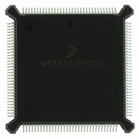
MC68302EH20C Freescale Semiconductor, MC68302EH20C Datasheet - Page 414

MC68302EH20C
Manufacturer Part Number
MC68302EH20C
Description
IC MPU MULTI-PROTOCOL 132-PQFP
Manufacturer
Freescale Semiconductor
Datasheets
1.MC68302AG20C.pdf
(4 pages)
2.MC68302AG20C.pdf
(2 pages)
3.MC68302AG20C.pdf
(13 pages)
4.MC68302EH20C.pdf
(481 pages)
Specifications of MC68302EH20C
Processor Type
M683xx 32-Bit
Speed
20MHz
Voltage
5V
Mounting Type
Surface Mount
Package / Case
132-MQFP, 132-PQFP
Family Name
M68000
Device Core
ColdFire
Device Core Size
32b
Frequency (max)
20MHz
Instruction Set Architecture
RISC
Supply Voltage 1 (typ)
5V
Operating Temp Range
0C to 70C
Operating Temperature Classification
Commercial
Mounting
Surface Mount
Pin Count
132
Package Type
PQFP
Lead Free Status / RoHS Status
Lead free / RoHS Compliant
Features
-
Lead Free Status / Rohs Status
Compliant
Available stocks
Company
Part Number
Manufacturer
Quantity
Price
Company:
Part Number:
MC68302EH20C
Manufacturer:
Freescale Semiconductor
Quantity:
10 000
Part Number:
MC68302EH20C
Manufacturer:
FREESCALE
Quantity:
20 000
Company:
Part Number:
MC68302EH20CB1
Manufacturer:
Freescale Semiconductor
Quantity:
10 000
Company:
Part Number:
MC68302EH20CR2
Manufacturer:
Freescale Semiconductor
Quantity:
10 000
- MC68302AG20C PDF datasheet
- MC68302AG20C PDF datasheet #2
- MC68302AG20C PDF datasheet #3
- MC68302EH20C PDF datasheet #4
- Current page: 414 of 481
- Download datasheet (2Mb)
MC68302 Applications
There is nothing to synchronize on the receive side. As soon as the ENR bit is set, the first
time slot for this SCC will begin the reception process. As with the NMSI mode, a word is
not written to the buffer until the 9th clock after the serial clock that clocked in the last bit of
this word (see D.8.7 Gating Clocks in NMSI Mode). Recall that clocks can only be counted
during time slots.
D.8.9 PCM Mode Final Thoughts
Since all synchronous protocols work with PCM mode, it is possible to use the regular BI-
SYNC mode to send syncs in the data stream, as described earlier.
When using totally transparent mode with PCM, both the NTSYN and EXSYN bits should
normally be set. The DIAG1-DIAG0 bits can be set for either normal mode or software op-
eration with no difference in behavior.
PCM mode does affect the SCCS register. In the SCCS register, the CD and CTS bits are
always zero when the ENR and ENT bits, respectively, are set. The ID bit is not valid in
transparent mode, regardless of the physical interface chosen.
Care should always be taken to avoid glitches or ringing on the L1CLK line. If a glitched or
ringing L1CLK line causes an extra clock to be inserted during a time slot, there is no way
to resynchronize the byte alignment in envelope mode until the ENT synchronization algo-
rithm described previously is followed. This potential problem does lead to one slight advan-
tage of the one-clock-prior method over the envelope sync. With the one-clock-prior method,
it is more likely that the glitched clock will only misalign the transfer/reception of a single byte
of data, rather than the whole data stream. (However, this cannot be guaranteed—predict-
ing device behavior out-of-spec is extremely difficult.)
D.8.10 Using Transparent Mode with IDL and GCI
Transparent mode can be freely used with the ISDN physical interfaces. Using transparent
mode with the ISDN interfaces is especially useful in the B-channels, since the D channel
LAPD protocol is typically supported with the SCC in HDLC mode. Transparent data may be
sent and received over the 64-kbps B1 channel, the 64-kbps B2 channel, a combined B1-
B2 channel with a 128-kbps bandwidth, or subportions of either the B1 or B2 channel or
both. (The desired subportions are defined in the SIMASK register.)
With the ISDN interfaces, as with the other types of interfaces, if the SCC is not transmitting
data, it will transmit $FFs. If the NTSYN and the EXSYN bits are set in the SCM, data will
be byte-aligned within the B1 or B2 channels. Thus, it will only be transmitted once the SCC
transmit FIFO is filled and the beginning of the B1 or B2 channel occurs.
A special case occurs when the B1 and B2 channels are combined into a single 128-kbps
channel. In this case, although data will only appear on byte boundaries, the transmit buff-
er's data could begin in either the B1 or B2 channels, depending on the timing involved. If
this is a problem, the following rule may be observed. If the ENT bit is set at a consistent
time during the GCI/IDL frame and if ready bit of the Tx BD is set at a consistent time relative
to the GCI/IDL frame (preferably before the ENT bit is set), a consistent starting point of byte
alignment (either B1 or B2) can be obtained. If data is then transmitted in a continuous
D-64
MC68302 USER’S MANUAL
MOTOROLA
Related parts for MC68302EH20C
Image
Part Number
Description
Manufacturer
Datasheet
Request
R
Part Number:
Description:
Manufacturer:
Freescale Semiconductor, Inc
Datasheet:

Part Number:
Description:
MC68302 Configuring the Chip Selects on the MC68302
Manufacturer:
Motorola / Freescale Semiconductor

Part Number:
Description:
MC68302 Design Concept - Expanding Interrupts on the MC68302
Manufacturer:
Motorola / Freescale Semiconductor

Part Number:
Description:
MC68302 MC68302 Adapting a WAN Controller to a LAN Environment
Manufacturer:
Motorola / Freescale Semiconductor

Part Number:
Description:
MC68302 EKB Applications - Power Measurements on the MC68302
Manufacturer:
Motorola / Freescale Semiconductor

Part Number:
Description:
MC68302 Interfacing the MC68020 to a Slave MC68302
Manufacturer:
Motorola / Freescale Semiconductor

Part Number:
Description:
MC68302 MC68302 Software Performance
Manufacturer:
Motorola / Freescale Semiconductor

Part Number:
Description:
MC68302 Evaluating EDX on the ADS302
Manufacturer:
Motorola / Freescale Semiconductor

Part Number:
Description:
MC68302 Design Advisory #1 - MC68SC302 Passive ISDN Protocol Engine
Manufacturer:
Motorola / Freescale Semiconductor

Part Number:
Description:
MC68302, MC68360, and MPC860 Characteristics and Design Notes for Crystal Feedback Oscillators
Manufacturer:
Motorola / Freescale Semiconductor
Part Number:
Description:
Mc68302 Integrated Multi-protocol Processor
Manufacturer:
Freescale Semiconductor, Inc
Datasheet:
Part Number:
Description:
Manufacturer:
Freescale Semiconductor, Inc
Datasheet:
Part Number:
Description:
Manufacturer:
Freescale Semiconductor, Inc
Datasheet:
Part Number:
Description:
Manufacturer:
Freescale Semiconductor, Inc
Datasheet:
Part Number:
Description:
Manufacturer:
Freescale Semiconductor, Inc
Datasheet:


